All about ir arduino - cool
?Download as DOCX, PDF?
1 like?217 views

This document provides a tutorial on using an Arduino and infrared remote controls. It discusses using an infrared receiver module like the TSOP4138 to receive signals from a remote and translate the codes using an IR library. Example code is provided to receive codes on the serial monitor and to display the button pressed on an LCD screen based on the code received. The tutorial explains how infrared signals work and provides guidance on wiring up the receiver and using the library to interpret button presses from a remote control.

All about ir arduino - cool
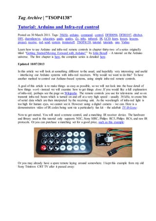
- 1. Tag Archive | "TSOP4138" Tutorial: Arduino and Infra-red control Posted on 30 March 2011. Tags: 38kHz, arduino, command, control, DFR0094, DFR0107, dfrobot, DIY, duemilanove, education, guide, guides, i2c, infra, infrared, IR, LCD, learn, lesson, lessons, project, receive, red, send, system, tronixstuff, TSOP4138, tutorial, tutorials, uno, Vishay Learn how to use Arduino and infra-red remote controls in chapter thirty-two of a series originally titled °∞Getting Started/Moving Forward with Arduino!°± by John Boxall ®C A tutorial on the Arduino universe. The first chapter is here, the complete series is detailed here. Updated 10/07/2013 In this article we will look at something different to the usual, and hopefully very interesting and useful ®C interfacing our Arduino systems with infra-red receivers. Why would we want to do this? To have another method to control our Ardiuno-based systems, using simple infra-red remote controls. A goal of this article is to make things as easy as possible, so we will not look into the base detail of how things work - instead we will examine how to get things done. If you would like a full explanation of infra-red, perhaps see the page on Wikipedia. The remote controls you use for televisions and so on transmit infra-red beam which is turned on and off at a very high speed ®C usually 38 kHz, to create bits of serial data which are then interpreted by the receiving unit. As the wavelength of infra-red light is too high for human eyes, we cannot see it. However using a digital camera ®C we can. Here is a demonstration video of IR codes being sent via a particularly fun kit ®C the adafruit TV-B-Gone: Now to get started. You will need a remote control, and a matching IR receiver device. The hardware and library used in this tutorial only supports NEC, Sony SIRC, Philips RC5, Philips RC6, and raw IR protocols. Or you can purchase a matching set for a good price, such as this example: Or you may already have a spare remote laying around somewhere. I kept this example from my old Sony Trinitron CRT TV after it passed away:
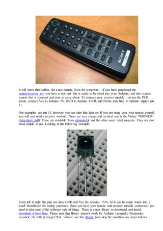
- 2. It will more than suffice for a test remote. Now for a receiver ®C if you have purchased the remote/receiver set, you have a nice unit that is ready to be wired into your Arduino, and also a great remote that is compact and easy to carry about. To connect your receiver module ®C as per the PCB labels, connect Vcc to Arduino 5V, GND to Arduino GND, and D (the data line) to Arduino digital pin 11. Our examples use pin 11, however you can alter that later on. If you are using your own remote control, you will just need a receiver module. These are very cheap, and an ideal unit is the Vishay TSOP4138 (data sheet .pdf). These are available from element-14 and the other usual retail suspects. They are also dead-simple to use. Looking at the following example: From left to right the pins are data, GND and Vcc (to Arduino +5V). So it can be easily wired into a small breadboard for testing purposes. Once you have your remote and receiver module connected, you need to take care of the software side of things. There is a new library to download and install, download it from here. Please note that library doesn°Øt work for Arduino Leonardo, Freetronics Leostick, etc with ATmega32U4. Instead, use this library (and skip the modification steps below).
- 3. Extract the IRremote folder and place into the ..arduinoxxxlibraries folder. Then restart your Arduino IDE if it was already open. Using Arduino IDE v1.0 or greater? Open the file °∞IRRemoteInt.h°± in the library folder, and change the line #include "WProgram.h" to #include "Arduino.h" 1 2 3 4 #include "WProgram.h" to #include "Arduino.h" Then save and close the file, restart the Arduino IDE and you°Øre set. With our first example, we will receive the commands from our remote control and display them on the serial monitor: // example 32.1 - IR receiver code repeater // http://tronixstuff.com/tutorials > chapter 32 // based on code by Ken Shirriff - http://arcfn.com #include <IRremote.h> // use the library int receiver = 11; // pin 1 of IR receiver to Arduino digital pin 11 IRrecv irrecv(receiver); // create instance of 'irrecv' decode_results results; void setup() { Serial.begin(9600); // for serial monitor output irrecv.enableIRIn(); // Start the receiver } void loop() {
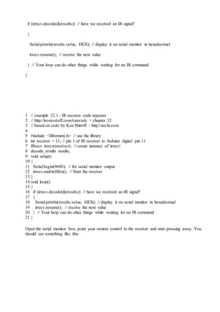
- 4. if (irrecv.decode(&results)) // have we received an IR signal? { Serial.println(results.value, HEX); // display it on serial monitor in hexadecimal irrecv.resume(); // receive the next value } // Your loop can do other things while waiting for an IR command } 1 2 3 4 5 6 7 8 9 10 11 12 13 14 15 16 17 18 19 20 21 // example 32.1 - IR receiver code repeater // http://tronixstuff.com/tutorials > chapter 32 // based on code by Ken Shirriff - http://arcfn.com #include <IRremote.h> // use the library int receiver = 11; // pin 1 of IR receiver to Arduino digital pin 11 IRrecv irrecv(receiver); // create instance of 'irrecv' decode_results results; void setup() { Serial.begin(9600); // for serial monitor output irrecv.enableIRIn(); // Start the receiver } void loop() { if (irrecv.decode(&results)) // have we received an IR signal? { Serial.println(results.value, HEX); // display it on serial monitor in hexadecimal irrecv.resume(); // receive the next value } // Your loop can do other things while waiting for an IR command } Open the serial monitor box, point your remote control to the receiver and start pressing away. You should see something like this:
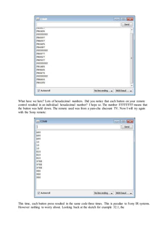
- 5. What have we here? Lots of hexadecimal numbers. Did you notice that each button on your remote control resulted in an individual hexadecimal number? I hope so. The number FFFFFFFF means that the button was held down. The remote used was from a yum-cha discount TV. Now I will try again with the Sony remote: This time, each button press resulted in the same code three times. This is peculiar to Sony IR systems. However nothing to worry about. Looking back at the sketch for example 32.1, the
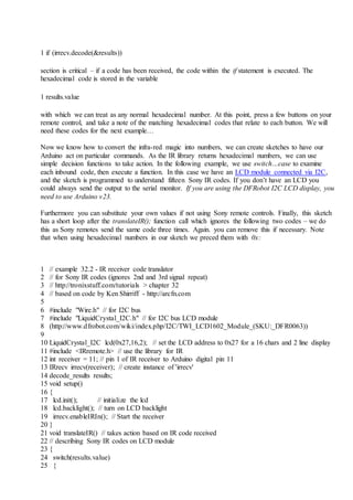
- 6. 1 if (irrecv.decode(&results)) section is critical ®C if a code has been received, the code within the if statement is executed. The hexadecimal code is stored in the variable 1 results.value with which we can treat as any normal hexadecimal number. At this point, press a few buttons on your remote control, and take a note of the matching hexadecimal codes that relate to each button. We will need these codes for the next example°≠ Now we know how to convert the infra-red magic into numbers, we can create sketches to have our Arduino act on particular commands. As the IR library returns hexadecimal numbers, we can use simple decision functions to take action. In the following example, we use switch°≠case to examine each inbound code, then execute a function. In this case we have an LCD module connected via I2C, and the sketch is programmed to understand fifteen Sony IR codes. If you don°Øt have an LCD you could always send the output to the serial monitor. If you are using the DFRobot I2C LCD display, you need to use Arduino v23. Furthermore you can substitute your own values if not using Sony remote controls. Finally, this sketch has a short loop after the translateIR(); function call which ignores the following two codes ®C we do this as Sony remotes send the same code three times. Again. you can remove this if necessary. Note that when using hexadecimal numbers in our sketch we preced them with 0x: 1 2 3 4 5 6 7 8 9 10 11 12 13 14 15 16 17 18 19 20 21 22 23 24 25 // example 32.2 - IR receiver code translator // for Sony IR codes (ignores 2nd and 3rd signal repeat) // http://tronixstuff.com/tutorials > chapter 32 // based on code by Ken Shirriff - http://arcfn.com #include "Wire.h" // for I2C bus #include "LiquidCrystal_I2C.h" // for I2C bus LCD module (http://www.dfrobot.com/wiki/index.php/I2C/TWI_LCD1602_Module_(SKU:_DFR0063)) LiquidCrystal_I2C lcd(0x27,16,2); // set the LCD address to 0x27 for a 16 chars and 2 line display #include <IRremote.h> // use the library for IR int receiver = 11; // pin 1 of IR receiver to Arduino digital pin 11 IRrecv irrecv(receiver); // create instance of 'irrecv' decode_results results; void setup() { lcd.init(); // initialize the lcd lcd.backlight(); // turn on LCD backlight irrecv.enableIRIn(); // Start the receiver } void translateIR() // takes action based on IR code received // describing Sony IR codes on LCD module { switch(results.value) {
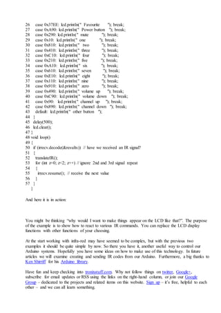
- 7. 26 27 28 29 30 31 32 33 34 35 36 37 38 39 40 41 42 43 44 45 46 47 48 49 50 51 52 53 54 55 56 57 case 0x37EE: lcd.println(" Favourite "); break; case 0xA90: lcd.println(" Power button "); break; case 0x290: lcd.println(" mute "); break; case 0x10: lcd.println(" one "); break; case 0x810: lcd.println(" two "); break; case 0x410: lcd.println(" three "); break; case 0xC10: lcd.println(" four "); break; case 0x210: lcd.println(" five "); break; case 0xA10: lcd.println(" six "); break; case 0x610: lcd.println(" seven "); break; case 0xE10: lcd.println(" eight "); break; case 0x110: lcd.println(" nine "); break; case 0x910: lcd.println(" zero "); break; case 0x490: lcd.println(" volume up "); break; case 0xC90: lcd.println(" volume down "); break; case 0x90: lcd.println(" channel up "); break; case 0x890: lcd.println(" channel down "); break; default: lcd.println(" other button "); } delay(500); lcd.clear(); } void loop() { if (irrecv.decode(&results)) // have we received an IR signal? { translateIR(); for (int z=0; z<2; z++) // ignore 2nd and 3rd signal repeat { irrecv.resume(); // receive the next value } } } And here it is in action: You might be thinking °∞why would I want to make things appear on the LCD like that?°±. The purpose of the example is to show how to react to various IR commands. You can replace the LCD display functions with other functions of your choosing. At the start working with infra-red may have seemed to be complex, but with the previous two examples it should be quite simple by now. So there you have it, another useful way to control our Arduino systems. Hopefully you have some ideas on how to make use of this technology. In future articles we will examine creating and sending IR codes from our Arduino. Furthermore, a big thanks to Ken Shirriff for his Arduino library. Have fun and keep checking into tronixstuff.com. Why not follow things on twitter, Google+, subscribe for email updates or RSS using the links on the right-hand column, or join our Google Group ®C dedicated to the projects and related items on this website. Sign up ®C it°Øs free, helpful to each other ®C and we can all learn something.
- 8. Arduino Tutorials Click for Detailed Chapter Index Chapters 0 1 2 3 4 Chapters 5 6 6a 7 8 Chapters 9 10 11 12 13 Ch. 14 - XBee Ch. 15 - RFID - RDM-630 Ch. 15a - RFID - ID-20 Ch. 16 - Ethernet Ch. 17 - GPS - EM406A Ch. 18 - RGB matrix - awaiting update Ch. 19 - GPS - MediaTek 3329 Ch. 20 - I2C bus part I Ch. 21 - I2C bus part II Ch. 22 - AREF pin Ch. 23 - Touch screen Ch. 24 - Monochrome LCD Ch. 25 - Analog buttons Ch. 26 - GSM - SM5100 Uno Ch. 27 - GSM - SM5100 Mega Ch. 28 - Colour LCD Ch. 29 - TFT LCD touch screen Ch. 30 - Arduino + twitter Ch. 31 - Inbuilt EEPROM Ch. 32 - Infra-red control Ch. 33 - Control AC via SMS Ch. 34 - SPI bus part I Ch. 35 - Video-out Ch. 36 - SPI bus part II Ch. 37 - Timing with millis() Ch. 38 - Thermal Printer Ch. 39 - NXP SAA1064 Ch. 40 - Push wheel switches Ch. 40a - Wheel switches II Ch. 41 - More digital I/O Ch. 42 - Numeric keypads Ch. 43 - Port Manipulation - Uno Ch. 44 - ATtiny+Arduino Ch. 45 - Ultrasonic Sensor Ch. 46 - Analog + buttons II Ch. 47 - Internet-controlled relays Ch. 48 - MSGEQ7 Spectrum Analyzer First look - Arduino Due Ch. 49 - KTM-S1201 LCD modules Ch. 50 - ILI9325 colour TFT LCD modules Ch. 51 - MC14489 LED display driver IC Ch. 52 - NXP PCF8591 ADC/DAC IC Ch. 53 - TI ADS1110 16-bit ADC IC Ch. 54 - NXP PCF8563 RTC
- 9. Ch. 55 - GSM - SIM900 Ch. 56 - MAX7219 LED driver IC Ch. 57 - TI TLC5940 LED driver IC Ch. 58 - Serial PCF8574 LCD Backpacks Arduino Y®≤n tutorials pcDuino tutorials The Arduino Book Interesting Sites David L. Jones' eev blog Freetronics Arduino Geniuses! Silicon Chip magazine Always a great read! Talking Electronics Amazing Arduino Shield Directory Dangerous Prototypes The Amp Hour podcast EEWeb Elec Engineering Forum Superhouse.tv High-tech home renovation Mr Dick Smith OA .