Welding
- 1. Welding
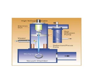
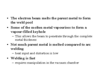
- 2. ELECTRON BEAM WELDING •The electron beam gun has a tungsten filament which is heated, freeing electrons. •The electrons are accelerated from the source with high voltage potential between a cathode and anode. •The stream of electrons then pass through a hole in the anode. The beam is directed by magnetic forces of focusing and deflecting coils. This beam is directed out of the gun column and strikes the workpiece. •The potential energy of the electrons is transferred to heat upon impact of the workpiece and cuts a perfect hole at the weld joint. Molten metal fills in behind the beam, creating a deep finished weld. Fusion of base metals eliminates the need for filler metals. The vacuum requirement for operation of the electron beam equipment eliminates the need for shielding gases and fluxes
- 5. Advantages • Maximum amount of weld penetration with the least amount of heat input reduces distortion • Electron beam welding often reduces the need for secondary operations • Repeatability is achieved through electrical control systems • A cleaner, stronger and homogeneous weld is produced in a vacuum • The electron beam machine's vacuum environment eliminates atmospheric contaminates in the weld • Exotic alloys and dissimilar materials can be welded • Extreme precision due to CNC programming and magnification of operator viewing • Electron beam welding frequently yields a 0% scrap rate
- 6. Disadvantages • EBW is by far the most costly welding process; the equipment can cost hundreds of thousands to millions of dollars. • EBW requires a vacuum chamber containing a hard vacuum. • Only small to medium size items can be welded. Though the welding itself can be done very fast, overall EBW is time consuming. • The equipment is complex and there are quite a few process variables involved.
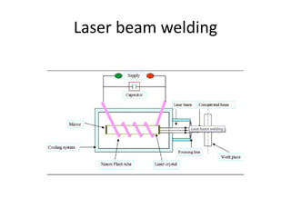
- 8. LASER BEAM WELDING • A laser beam is produced inside of the Ruby Crystal. The Ruby Crystal is made of aluminium oxide with chromium dispersed throughout it. • Which is forming about 1/2000 of crystal, this less than natural ruby. Silver coated mirrors are fitted internally in the both side of crystal. The one side of mirror has a tiny hole, a beam is come out through this hole. • A flash tube is placed around the Ruby Crystal, which is filled with xenon inert gas. • The flash is specially designed such as which is made flash rate about thousands flashes per seconds. • The electrical energy is converted into light energy, this is worked by flash tube. • The capacitor is provided for storage the electrical energy and supply the high voltage to flash tube for performed appropriately.
- 9. • The electrical energy discharged from capacitor and xenon transform the high energy into white flash light rate of 1/1000 per second. • The chromium atoms of Ruby Crystal are excited and pumped into high energy. Due to heat generating the some of this energy is lost. • But some light energy reflected mirror to mirror and again chromium atoms are excited until loss their extra energy simultaneously to form a narrow beam of coherent light. Which is come out through the one end tiny hole of crystal’s mirror. • This narrow beam is focused by a optical focusing lens to produce a small intense of laser on the job.
- 10. Advantages • Single pass weld penetration up to 3/4” in steel • High Travel speed • Materials need not be conductive • No filler metal required • Low heat input produces low distortion • Does not require a vacuum
- 11. Disadvantages • High initial start-up costs • Part fit-up and joint tracking are critical • Not portable • Metals such as copper and aluminum have high reflectivity and are difficult to laser weld • High cooling rates may lead to materials problems
- 12. Solid state welding • A group of welding processes which produces coalescence at temperatures essentially below the melting point of the base materials being joined, without the addition of brazing filler metal. • Pressure may or may not be used. These processes are sometimes erroneously called solid state bonding processes: this group of welding processes includes cold welding, diffusion welding, explosion welding, forge welding, friction welding, hot pressure welding, roll welding, and ultrasonic welding.
- 13. • Solid state welding includes some of the very oldest of the welding processes and some of the very newest. Some of the processes offer certain advantages since the base metal does not melt and form a nugget. • The metals being joined retain their original properties without the heat-affected zone problems involved when there is base metal melting. • When dissimilar metals are joined their thermal expansion and conductivity is of much less importance with solid state welding than with the arc welding processes
- 14. Cold welding • A solid state welding process which uses pressure at room temperature to produce coalescence of metals with substantial deformation at the weld. • Welding is accomplished by using extremely high pressures on extremely clean interfacing materials. Sufficiently high pressure can be obtained with simple hand tools when extremely thin materials are being joined. • When cold welding heavier sections a press is usually required to exert sufficient pressure to make a successful weld. • Indentations are usually made in the parts being cold welded. The process is readily adaptable to joining ductile metals. • Aluminum and copper are readily cold welded. Aluminum and copper can be joined together by cold welding
- 15. • At least one of the metals must be ductile without excessive work- hardening. • Total absence of applied heating. • Dissimilar metals can be joined. • Surface preparation is important. Characteristics of Cold Welding
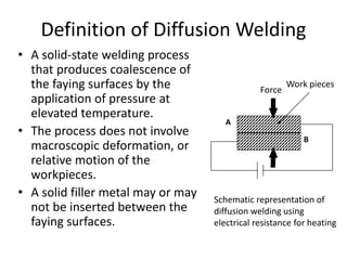
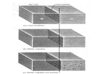
- 16. • A solid-state welding process that produces coalescence of the faying surfaces by the application of pressure at elevated temperature. • The process does not involve macroscopic deformation, or relative motion of the workpieces. • A solid filler metal may or may not be inserted between the faying surfaces. Work pieces Schematic representation of diffusion welding using electrical resistance for heating A B Force Definition of Diffusion Welding
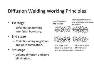
- 17. • 1st stage – deformation forming interfacial boundary. • 2nd stage – Grain boundary migration and pore elimination. • 3rd stage – Volume diffusion and pore elimination. asperities come into contact. 2nd stage grain boundary migration and pore elimination 1st stage deformation and interfacial boundary formation 3rd stage volume diffusion pore elimination Diffusion Welding Working Principles
- 19. A solid state welding process in which coalescence is produced at the faying surfaces by the application of high frequency vibratory energy while the work pieces are held together under moderately low static pressure. Definition of Ultrasonic Welding
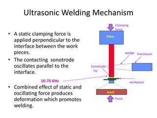
- 20. • A static clamping force is applied perpendicular to the interface between the work pieces. • The contacting sonotrode oscillates parallel to the interface. • Combined effect of static and oscillating force produces deformation which promotes welding. Anvil Mass Sonotrode tip Clamping force wedge Transducer Force workpiece Ultrasonic Welding Mechanism 10-75 KHz
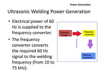
- 21. Ultrasonic Welding Power Generation • Electrical power of 60 Hz is supplied to the frequency converter. • The frequency converter converts the required 60 Hz signal to the welding frequency (from 10 to 75 kHz). Electrical energy Frequency converter Vibratory transducer Transducer Power Generation
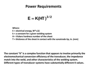
- 22. 2/3 )HT(KE  Where: E = electrical energy, W*s (J) k = a constant for a given welding system H = Vickers hardness number of the sheet T = thickness of the sheet in contact with the sonotrode tip, in. (mm) Power Requirements The constant “K” is a complex function that appears to involve primarily the electromechanical conversion efficiency of the transducer, the impedance match into the weld, and other characteristics of the welding system. Different types of transducer systems have substantially different K values.
- 23. • No heat is applied and no melting occurs. • Permits welding of thin to thick sections. • Welding can be made through some surface coatings. • Pressures used are lower, welding times are shorter, and the thickness of deformed regions are thinner than for cold welding. Advantages of Ultrasonic Welding
- 24. • The thickness of the component adjacent to the sonotrode tip must not exceed relatively thin gages because of power limitations of the equipment. • Process is limited to lap joints. • Butt welds can not be made because there is no means of supporting the workpieces and applying clamping force. Limitations of Ultrasonic Welding
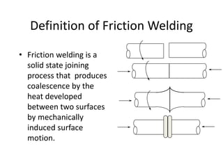
- 25. • Friction welding is a solid state joining process that produces coalescence by the heat developed between two surfaces by mechanically induced surface motion. Definition of Friction Welding
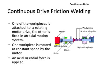
- 27. • One of the workpieces is attached to a rotating motor drive, the other is fixed in an axial motion system. • One workpiece is rotated at constant speed by the motor. • An axial or radial force is applied. Continuous Drive Workpieces Non-rotating viseMotor Chuck Spindle Hydraulic cylinder Brake Continuous Drive Friction Welding
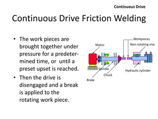
- 29. • The work pieces are brought together under pressure for a predeter- mined time, or until a preset upset is reached. • Then the drive is disengaged and a break is applied to the rotating work piece. Continuous Drive Workpieces Non-rotating viseMotor Chuck Spindle Hydraulic cylinder Brake Continuous Drive Friction Welding
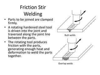
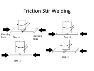
- 30. Friction Stir Welding • Parts to be joined are clamped firmly. • A rotating hardened steel tool is driven into the joint and traversed along the joint line between the parts. • The rotating tool produces friction with the parts, generating enough heat and deformation to weld the parts together. Butt welds Overlap welds
- 31. Friction Stir Welding Step -1 Step -2 Step -3 Step -4 clamping force Clamping force
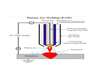
- 32. Plasma welding
- 34. WHAT IS PLASMA?
- 37. Copper introduction • Copper is second only to iron and steel in commercial importance. • It is of brownish red colour and posses the following properties • Resistance to corrosion. • Non magnetic properties. • Easy to work ,it is ductile and malleable • High thermal and electric conductivity
- 38. • Compared to with ferrous materials ,copper based material have • High thermal conductives • Greater thermal expansion coefficient, and some cases • Susceptibility to hot cracking • Oxidation • Fluidity of molten copper
- 39. • Higher thermal conductivity necessitates high heat input into the parental metal to raise the temperature sufficiently to produce the fusion desirable for most welding processes. • High input heat is provide by • High welding current • Nozzles tips of larger size • Copper has high thermal expansion coefficients are responsible for introduction of residual stresses in and around the joint • Preheating helps to minimize the thermal co efficient of expansion
- 40. • Suitable fixture are used to reduce the distortion in welding materials. • Copper has relatively low strength above 500deg ,therefore cracking may occur where severe stresses are introduced into the weldment. • Copper has a tendency to absorb oxygen in molten state . presence of oxygen tends to reduce the melting point and corrosion resistance and decrease the mechanical properties
- 41. • Usage of flux or inert gas is necessary to avoid the oxidation. • Greater welding speeds should be used for copper and its alloys than is practical for steel
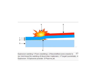
- 42. Explosion welding (EXW) • A solid state process where welding is accomplished by accelerating one of the components at extremely high velocity through the use of chemical explosives. This process is most commonly utilized to clad carbon steel plate with a thin layer o f corrosion resistant material (e.g., stainless steel, nickel alloy, titanium, or zirconium). Due to the nature of this process, producible geometries are very limited. They must be simple. Typical geometries produced include plates, tubing and tubeshe
Editor's Notes
- Cold welding requires one of the joining metals be ductile and not subject to rapid work hardening. No external heating is required. Surface preparation is usually performed prior to welding. Dissimilar metals can be joined.
- Two necessary conditions must be met before a satisfactory diffusion weld can be made. They are: (a) Mechanical intimacy of the faying surfaces. (b) Disruption and dispersion of surface contaminants Stage 1 involves deformation of asperities. This deformation may be temperature and time dependent, similar to creep. Stage 2 includes boundary migration, recrystallization, and pore size reduction. Stage 3 involves bulk diffusion phenomenon including oxide and contaminant desolution, and further pore size reduction.
- In the general case, one part is held fixed while the other is rotated. When the two parts are brought into contact, the frictional heat generated breaks down the surface asperities under the action of the load, and surface material is plastically moved out of the interface, carrying with it any surface oxide and contamination into the outside “flash” material (gray in this figure). This flash material may or may not be subsequently machined off depending upon the final use of the part.
- In continuous “direct drive” friction welding, one workpiece is attached to a rotating motor drive unit as shown above. The other workpiece is clamped in a non-rotating axial drive unit. The two workpieces are gradually brought together with one rotating and the other still. When they make contact, heat is generated at the interface due to friction. Additional axial force is applied. The axial force is raised to a final constant value and held for a predetermined time, or until a preset amount of upset takes place. The rotational driving force is disconnected, and the rotating workpiece is stopped by the application of a braking force. The axial force (forging force) is maintained or increased for a predetermined time after rotation ceases.
- Continuation of previous slide
- Unlike conventional friction welding, the parts to be joined by friction stir welding are not rotated. The parts are clamped firmly in a restraining device. A rotating tool traverses along the joint line. During rotation, the tool generates frictional heating, deformation, and welding along the joint line of the workpieces. Butt joints, corner joints, T joints, and fillet-butt joints can be welded by friction stir welding.

