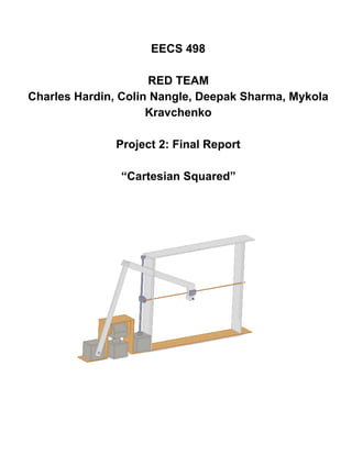
Hands-on Robotics_Robotic Arm
- 2. CONTENT╠² ╠² 1. Background╠² 1.1. Project╠²Introduction╠² 1.2. Equipment╠²Involved╠² 1.2.1. Computer╠²Vision╠²System╠² 1.2.2. Dynamixel╠²RX┬Ł64╠²and╠²EX┬Ł106╠²Servo╠²Motors╠² 1.3. Design╠²brainstorming╠² 1.3.1. Hardware╠² 1.3.1.1. SCARA╠²Robot╠² 1.3.1.2. R4╠²Robot╠² 1.3.1.3. Cartesian╠²Robot╠² 1.3.2. Software╠² 2. Implementation╠² 2.1. Initial╠²Concept╠² 2.2. Robot╠²Design╠²and╠²Construction╠² 2.3. Design╠²Considerations╠² 2.3.1. Sources╠²of╠²Error╠² 2.3.2. Re┬Łevaluation╠²and╠²Modifications╠² 2.4. Motion╠²Algorithm╠² 2.4.1. Robot╠² 2.4.2. Manual╠²Controller╠² 2.4.3. Autonomous╠²Controller╠² 3. Expected╠²Performance╠² 3.1. Modelling╠²Software╠² 3.2. Calibration╠²and╠²Modification╠² 4. Results╠² 4.1. P┬ŁDay╠²Results╠² 4.2. Observations╠² 5. Discussion╠² 5.1. Discussion╠²of╠²Other╠²Teams╠² 5.2. Reflection╠²on╠²Current╠²Design╠² 5.2.1. Mechanical╠²Design╠² 5.2.2. Software╠² 5.3. Future╠²Modifications╠² 5.3.1. Mechanical╠²Design╠² 5.3.2. Software╠² 6. References╠² 7. Appendix╠²
- 3. ╠² ╠² 1. Background╠² 1.1. Project╠²Introduction╠² ╠² Our╠²task╠²was╠²to╠²build╠²a╠²robot╠²arm╠²which╠²is╠²capable╠²of╠²drawing╠²on╠²a╠²piece╠² of╠²paper╠²within╠²a╠²1╠²ft.┬│╠²workspace.╠²There╠²were╠²several╠²paper╠²positions╠²and╠² orientations,╠²which╠²were╠²not╠²known╠²in╠²advance╠²except╠²for╠²the╠²following╠² properties:╠² (1)╠²the╠²paper╠²is╠²a╠²standard╠²sheet╠²of╠²letter╠²paper,╠²laid╠²on╠²a╠²rigid╠²backing,╠² entirely╠²within╠²the╠²workspace═Š╠² (2)╠²the╠²paper╠²must╠²face╠²upwards╠²or╠²at╠²most╠²5┬░╠²downwards.╠² (3)╠²the╠²paper╠²must╠²face╠²within╠²90┬░╠²of╠²a╠²designated╠²ŌĆ£frontŌĆØ╠²direction.╠² ╠²╠² Before╠²attempting╠²to╠²draw╠²on╠²each╠²orientation,╠²our╠²team╠²was╠²allowed╠²to╠²calibrate╠²the╠²robot╠²by╠² hand,╠²by╠²moving╠²it╠²to╠²known╠²points╠²on╠²the╠²paper.╠²We╠²were╠²required╠²to╠²draw╠²a╠²four╠²by╠²four╠²inch╠² square,╠²with╠²sides╠²parallel╠²to╠²the╠²edges╠²of╠²the╠²paper.╠²In╠²addition,╠²the╠²instructor╠²provided╠²a╠²sequence╠² of╠²pen╠²strokes╠²as╠²a╠²list╠²of╠²two┬Łdimensional╠²positions╠²relative╠²to╠²the╠²corner╠²of╠²the╠²page.╠²The╠²robot╠²arm╠² had╠²to╠²also╠²draw╠²these╠²pen╠²strokes╠²on╠²the╠²page.╠² ╠² 1.2. Equipment╠²Involved╠² 1.2.1. Computer╠²System╠² The╠²robot╠²was╠²controlled╠²via╠²a╠²JoyApp╠²written╠²in╠²python╠²and╠²running╠²on╠²a╠²linux╠²machine.╠²The╠² computer╠²communicated╠²with╠²the╠²robot╠²via╠²RS485╠²serial╠²connection.╠²╠² ╠² 1.2.2. Dynamixel╠²RX┬Ł64╠²and╠²MX┬Ł64╠²Servo╠²Motors╠² Servo╠²motors╠²were╠²provided╠²along╠²with╠²the╠²python╠²library.╠²These╠²motors╠²allowed╠²both╠²constant╠² rotation╠²and╠²joint╠²mode╠²operations,╠²where╠²prescribed╠²torque╠²between╠²┬Ł1╠²to╠²+1╠²or╠²prescribed╠²angles╠² between╠²┬Ł10000╠²to╠²10000╠²could╠²be╠²specified.╠²Maximum╠²of╠²6╠²servo╠²motors╠²(a╠²combination╠²of╠²RX┬Ł64╠² and╠²MX╠²motors)╠²were╠²allowed╠²in╠²any╠²suitable╠²configuration.╠² ╠² 1.3. Design╠²brainstorming╠² 1.3.1.╠²╠²╠²╠²Hardware╠² Group╠²brainstorming╠²meetings╠²focused╠²on╠²designing╠²a╠²robot╠²with╠²simplified╠²inverse╠²kinematics.╠² As╠²a╠²team╠²we╠²came╠²up╠²3╠²designs╠²satisfying╠²the╠²design╠²constraints╠²of╠²this╠²problem.╠²These╠²robot╠²ideas╠² are╠²as╠²follows:╠²╠² ╠² 1.3.1.1. Scara╠²(the╠²competition)╠²Robot╠² The╠²scara╠²(Selective╠²Compliance╠²Assembly╠²Robot╠²Arm)╠²is╠²an╠²RRRPR╠²style╠²robot╠²arm╠²that╠²is╠² typically╠²used╠²in╠²industrial╠²robotics.╠²The╠²arm╠²is╠²rigid╠²in╠²the╠²z╠²axis╠²and╠²pliable╠²in╠²the╠²X┬ŁY╠²axes.╠²In╠²order╠²
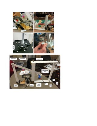
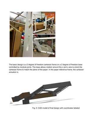
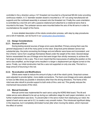
- 9. ╠² controlled╠²in╠²the╠²y╠²direction╠²using╠²a╠²1/4ŌĆØ╠²threaded╠²rod╠²mounted╠²to╠²a╠²Dynamixel╠²MX┬Ł64╠²motor╠²providing╠² continuous╠²rotation.╠²A╠²┬╝ŌĆØ╠²diameter╠²wooden╠²dowel╠²is╠²mounted╠²to╠²a╠²1/4ŌĆØ╠²nut╠²using╠²manufactured╠²rail╠² supports╠²and╠²the╠²nut/dowel╠²assembly╠²is╠²screwed╠²onto╠²the╠²threaded╠²rod.╠²Finally╠²the╠²x┬Łaxis╠²orientation╠² is╠²controlled╠²by╠²a╠²two╠²link╠²arm╠²with╠²a╠²passive╠²rotational╠²joint╠²attached╠²to╠²a╠²rotational╠²servo╠²that╠²is╠² mounted╠²to╠²the╠²base.╠²The╠²cartesian╠²servos╠²were╠²mounted╠²below╠²the╠²axis╠²of╠²the╠²tilt╠²servo╠²in╠²order╠²to╠² counterbalance╠²the╠²weight╠²of╠²the╠²frame.╠²╠² ╠² A╠²more╠²detailed╠²description╠²of╠²the╠²robots╠²construction╠²process,╠²with╠²step╠²by╠²step╠²procedures╠² and╠²a╠²bill╠²of╠²materials,╠²can╠²be╠²found╠²in╠²our╠²construction╠²documentation.╠²╠² ╠² 2.2. Design╠²Considerations╠² 2.2.1. Sources╠²of╠²Error╠² During╠²testing╠²several╠²sources╠²of╠²large╠²errors╠²were╠²identified.╠²Primary╠²among╠²them╠²was╠²the╠² general╠²sloppyness╠²in╠²all╠²of╠²the╠²many╠²joints╠²on╠²the╠²robot.╠²Snap┬Łlock╠²joints╠²between╠²servos╠²had╠² substantial╠²play,╠²the╠²joints╠²connecting╠²the╠²linkage╠²and╠²end╠²effector╠²were╠²loose╠²and╠²inconsistent,╠²and╠² the╠²U┬Łframe╠²/╠²servo╠²horn╠²couplings╠²themselves╠²flexed╠²under╠²the╠²weight╠²of╠²the╠²robot.╠²Several╠²design╠² factors╠²necessitated╠²the╠²use╠²of╠²linkage╠²arms╠²that╠²were╠²longer╠²than╠²strictly╠²necessary╠²to╠²achieve╠²the╠² full╠²range╠²of╠²motion╠²in╠²the╠²x╠²axis.╠²This╠²in╠²turn╠²meant╠²that╠²the╠²inaccuracies╠²of╠²setting╠²the╠²position╠²on╠²the╠² servo╠²was╠²amplified,╠²as╠²the╠²longer╠²arms╠²resulted╠²in╠²a╠²larger╠²x╠²displacement╠²per╠²degree╠²turned╠²on╠²the╠² servo.╠²Finally,╠²our╠²initial╠²construction╠²had╠²the╠²x╠²axis╠²rod╠²supported╠²on╠²only╠²one╠²side.╠²This╠²led╠²to╠²a╠² large╠²amount╠²of╠²bouncing╠²in╠²the╠²rod.╠²╠² ╠² 2.2.2. Re┬Łevaluation╠²and╠²Modifications╠² Efforts╠²were╠²made╠²to╠²reduce╠²the╠²amount╠²of╠²play╠²in╠²all╠²of╠²the╠²robotŌĆÖs╠²joints.╠²Snap┬Łlock╠²screws╠² were╠²adjusted╠²to╠²provide╠²tighter,╠²more╠²stable╠²connections.╠²The╠²foam┬Łcore╠²linkage╠²arms╠²were╠²adjusted╠² to╠²have╠²as╠²little╠²stress╠²as╠²possible╠²in╠²directions╠²other╠²than╠²the╠²driving╠²directions.╠²The╠²frame╠²of╠²the╠² robot╠²was╠²also╠²rebuilt╠²to╠²provide╠²support╠²to╠²both╠²ends╠²of╠²the╠²x╠²axis╠²rod.╠²This╠²greatly╠²reduces╠²the╠² mechanical╠²inaccuracies╠²of╠²the╠²robot.╠²╠² ╠² 2.3. Manual╠²Controller╠² Manual╠²control╠²was╠²implemented╠²for╠²each╠²servo╠²using╠²the╠²KORG╠²Midi╠²board.╠²The╠²tilt╠²and╠² rotate╠²servos╠²were╠²allowed╠²to╠²be╠²set╠²up╠²during╠²our╠²calibration╠²stage╠²for╠²each╠²paper╠²orientation,╠²so╠²no╠² further╠²implementation╠²was╠²done.╠²To╠²prevent╠²jitter╠²in╠²the╠²servo╠²motion╠²from╠²destroying╠²our╠²robot,╠²the╠² speed╠²of╠²each╠²servo╠²was╠²set╠²to╠²0.2,╠²to╠²create╠²a╠²very╠²smooth╠²motion.╠²This╠²introduced╠²significant╠²delay╠² in╠²the╠²response,╠²but╠²it╠²completely╠²eliminated╠²human╠²jitter╠²when╠²moving╠²the╠²sliders,╠²which╠²improved╠² the╠²effect╠²of╠²control.╠²
- 10. Manual╠²override╠²was╠²always╠²available╠²during╠²autonomous╠²drawing╠²testing╠²for╠²safety╠²purposes.╠² The╠²implementation╠²of╠²the╠²manual╠²control╠²can╠²be╠²found╠²in╠²the╠²python╠²files╠²in╠²the╠²Red╠²team╠²project╠²2╠² wiki.╠² ╠²╠² 2.3.1.1. Autonomous╠²Controller╠² Autonomous╠²algorithms╠²were╠²activated╠²by╠²pressing╠²buttons╠²on╠²the╠²Midi╠²controller╠²and╠²the╠² keyboard.╠²Several╠²methods╠²were╠²implemented╠²for╠²square╠²drawing╠²and╠²arbitrary╠²point╠²following.╠²The╠² first╠²issue╠²that╠²we╠²worked╠²to╠²solve╠²was╠²absolute╠²y╠²position.╠²Since╠²the╠²MX╠²servo╠²only╠²gives╠²the╠²current╠² angle╠²as╠²a╠²reading,╠²there╠²needed╠²to╠²be╠²a╠²way╠²to╠²track╠²the╠²number╠²of╠²rotations╠²it╠²had╠²completed╠²to╠²get╠² the╠²height╠²of╠²the╠²pen.╠²The╠²threaded╠²rod╠²we╠²used╠²was╠²rated╠²at╠²20╠²rotations╠²per╠²inch,╠²so╠²if╠²we╠²could╠² count╠²the╠²number╠²of╠²rotations╠²from╠²an╠²arbitrary╠²zero╠²point,╠²we╠²could╠²determine╠²absolute╠²height.╠²The╠² first╠²method╠²we╠²implemented,╠²was╠²to╠²sample╠²the╠²angle╠²reading,╠²and╠²when╠²it╠²reached╠²a╠²certain╠²range╠² around╠²zero╠²to╠²count╠²that╠²as╠²a╠²rotation.╠²Then╠²when╠²the╠²angle╠²reading╠²became╠²either╠²positive╠²or╠² negative╠²90╠²degrees╠²we╠²get╠²the╠²direction╠²of╠²rotation,╠²and╠²we╠²reset╠²the╠²ŌĆ£full╠²rotationŌĆØ╠²counter╠²when╠²the╠² angle╠²reading╠²reaches╠²a╠²range╠²around╠²180╠²degrees.╠²The╠²prevailing╠²issues╠²with╠²this╠²method,╠²is╠²that╠²it╠² required╠²constant╠²sampling╠²of╠²the╠²servo.╠²This╠²limited╠²the╠²speed╠²at╠²which╠²the╠²servo╠²could╠²rotate,╠²since╠² we╠²needed╠²at╠²least╠²2╠²samples╠²every╠²rotation╠²to╠²not╠²lose╠²count.╠²Our╠²servos╠²would╠²also╠²frequently╠²lose╠² connection╠²with╠²the╠²computer,╠²causing╠²the╠²program╠²to╠²crash╠²and╠²the╠²servos╠²to╠²get╠²stuck.╠²Using╠²this╠² method╠²we╠²found╠²that╠²rapidly╠²reading╠²data╠²repeatedly╠²from╠²the╠²servos╠²was╠²not╠²a╠²very╠²robust╠²solution,╠² so╠²we╠²did╠²not╠²stick╠²with╠²turn╠²counting╠²and╠²the╠²MX.╠² Instead╠²of╠²turn╠²counting,╠²we╠²fixed╠²a╠²certain╠²torque╠²for╠²the╠²y╠²servo,╠²and╠²measured╠²the╠²amount╠²of╠² time╠²it╠²took╠²to╠²complete╠²a╠²full╠²rotation╠²at╠²that╠²torque.╠²Since╠²we╠²know╠²how╠²many╠²rotations╠²the╠²threaded╠² rod╠²has╠²per╠²inch,╠²and╠²we╠²found╠²the╠²time╠²for╠²one╠²rotation,╠²we╠²can╠²calculate╠²the╠²time╠²needed╠²to╠²move╠² an╠²arbitrary╠²height.╠²The╠²processor╠²was╠²commanded╠²to╠²sleep╠²during╠²rotation╠²for╠²a╠²specified╠²amount╠²of╠² time.╠²We╠²found╠²that╠²when╠²applying╠².3╠²torque╠²and╠²measuring╠²manually,╠²the╠²end╠²effector╠²moved╠²at╠² approximately╠²1.25s/inch.╠²This╠²speed╠²was╠²used╠²to╠²calculate╠²the╠²time╠²the╠²processor╠²should╠²sleep╠² when╠²trying╠²to╠²move╠²for╠²longer╠²vertical╠²distances.╠² Our╠²code╠²also╠²had╠²teach┬Łrepeat╠²functionality,╠²although╠²we╠²did╠²not╠²end╠²up╠²using╠²it╠²during╠² P┬ŁDay.╠²We╠²implemented╠²a╠²function╠²by╠²which╠²we╠²would╠²save╠²the╠²state╠²of╠²each╠²servo,╠²and╠²the╠²current╠² absolute╠²height╠²of╠²the╠²robot,╠²then╠²use╠²a╠²function╠²to╠²play╠²back╠²each╠²state╠²from╠²beginning╠²to╠²end.╠²╠² ╠² 3. Expected╠²Performance╠² 3.1. Modeling╠²Software╠² Our╠²modeling╠²was╠²done╠²in╠²MATLAB╠²using╠²the╠²open╠²source╠²Robotics╠²Toolbox.╠²The╠²Robotics╠² Toolbox╠²is╠²ideal╠²for╠²modeling╠²robot╠²arms.╠²It╠²provides╠²a╠²method╠²to╠²add╠²an╠²arbitrary╠²amount╠²of╠²either╠² rotational╠²or╠²prismatic╠²joints,╠²connected╠²by╠²links.╠²It╠²also╠²calculates╠²the╠²forward╠²kinematics╠²and╠²can╠²plot╠² the╠²arm,╠²as╠²well╠²as╠²motion╠²of╠²the╠²arm.╠²Unfortunately╠²there╠²is╠²a╠²limitation,╠²in╠²that╠²it╠²does╠²not╠²allow╠² branches╠²of╠²links╠²(two╠²links╠²coming╠²from╠²the╠²same╠²node).╠²This╠²limits╠²our╠²ability╠²to╠²have╠²a╠²good╠² representation╠²of╠²our╠²robot╠²using╠²this╠²software.╠²╠²
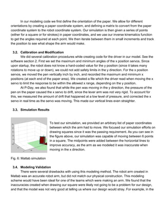
- 11. In╠²our╠²modeling╠²code╠²we╠²first╠²define╠²the╠²orientation╠²of╠²the╠²paper.╠²We╠²allow╠²for╠²different╠² orientations╠²by╠²creating╠²a╠²paper╠²coordinate╠²system,╠²and╠²defining╠²a╠²matrix╠²to╠²convert╠²from╠²the╠²paper╠² coordinate╠²system╠²to╠²the╠²robot╠²coordinate╠²system.╠²Our╠²simulation╠²is╠²then╠²given╠²a╠²series╠²of╠²points╠² (either╠²for╠²a╠²square╠²or╠²for╠²strokes)╠²in╠²paper╠²coordinates,╠²and╠²we╠²use╠²our╠²inverse╠²kinematics╠²function╠² to╠²get╠²the╠²angles╠²required╠²at╠²each╠²point.╠²We╠²then╠²iterate╠²between╠²them╠²in╠²small╠²increments╠²and╠²track╠² the╠²position╠²to╠²see╠²what╠²shape╠²the╠²arm╠²would╠²make.╠² ╠² 3.2. Calibration╠²and╠²Modification╠² We╠²did╠²several╠²calibration╠²procedures╠²while╠²creating╠²code╠²for╠²the╠²driver╠²in╠²our╠²model.╠²See╠²the╠² software╠²section╠²2.╠²First╠²we╠²set╠²the╠²maximum╠²and╠²minimum╠²angles╠²of╠²the╠²x╠²position╠²servos.╠²Since╠² upon╠²startup,╠²the╠²robot╠²does╠²not╠²know╠²a╠²hard┬Łcoded╠²value╠²for╠²the╠²y╠²position╠²(since╠²it╠²takes╠²many╠² rotations╠²to╠²move╠²up╠²or╠²down),╠²we╠²could╠²not╠²add╠²safety╠²limits╠²in╠²the╠²y╠²direction.╠²For╠²the╠²x╠²position╠² servos,╠²we╠²moved╠²the╠²pen╠²vertically╠²inch╠²by╠²inch,╠²and╠²recorded╠²the╠²maximum╠²and╠²minimum╠²x╠² positions╠²(at╠²each╠²end╠²of╠²the╠²paper╠²area).╠²We╠²created╠²a╠²file╠²which╠²the╠²driver╠²read╠²when╠²moving╠²the╠²x╠² servo╠²to╠²limit╠²the╠²response╠²to╠²be╠²within╠²the╠²allowed╠²x╠²range,╠²depending╠²on╠²the╠²y╠²position.╠²╠² At╠²P┬ŁDay,╠²we╠²also╠²found╠²that╠²while╠²the╠²pen╠²was╠²moving╠²in╠²the╠²y╠²direction,╠²the╠²pressure╠²of╠²the╠² pen╠²on╠²the╠²paper╠²caused╠²the╠²x╠²servo╠²to╠²drift,╠²since╠²the╠²lever╠²arm╠²was╠²not╠²very╠²rigid.╠²To╠²account╠²for╠² this,╠²we╠²measured╠²the╠²amount╠²of╠²drift╠²that╠²happened╠²at╠²a╠²low╠²level╠²of╠²pressure,╠²and╠²corrected╠²the╠²x╠² servo╠²in╠²real╠²time╠²as╠²the╠²servo╠²was╠²moving.╠²This╠²made╠²our╠²vertical╠²lines╠²even╠²straighter.╠² ╠² 3.3. Simulation╠²Results╠² ╠² ╠² To╠²test╠²our╠²simulation,╠²we╠²provided╠²an╠²arbitrary╠²list╠²of╠²paper╠²coordinates╠² between╠²which╠²the╠²arm╠²had╠²to╠²move.╠²We╠²focused╠²our╠²simulation╠²efforts╠²on╠² drawing╠²squares╠²since╠²it╠²was╠²the╠²passing╠²requirement.╠²As╠²you╠²can╠²see╠²in╠² the╠²figure╠²above,╠²our╠²simulation╠²was╠²capable╠²of╠²moving╠²between╠²6╠²points╠² in╠²a╠²square.╠²The╠²midpoints╠²were╠²added╠²between╠²the╠²horizontal╠²lines╠²to╠² improve╠²accuracy,╠²as╠²the╠²arm╠²as╠²we╠²modeled╠²it╠²was╠²inaccurate╠²when╠² moving╠²in╠²the╠²x╠²direction.╠² ╠² Fig.╠²6:╠²Matlab╠²simulation╠² ╠² 3.4. Modeling╠²Validation╠² There╠²were╠²several╠²drawbacks╠²with╠²using╠²this╠²modeling╠²method.╠²The╠²robot╠²arm╠²created╠²in╠² Matlab╠²was╠²an╠²accurate╠²robot╠²arm,╠²but╠²did╠²not╠²match╠²our╠²physical╠²construction.╠²This╠²modeling╠² scheme╠²would╠²have╠²been╠²ideal╠²for╠²one╠²of╠²the╠²teams╠²which╠²were╠²making╠²an╠²arm.╠²We╠²found╠²that╠²the╠² inaccuracies╠²created╠²when╠²drawing╠²our╠²square╠²were╠²likely╠²not╠²going╠²to╠²be╠²a╠²problem╠²for╠²our╠²design,╠² and╠²that╠²the╠²model╠²was╠²not╠²very╠²good╠²at╠²telling╠²us╠²where╠²our╠²design╠²would╠²stray.╠²For╠²example,╠²in╠²the╠²
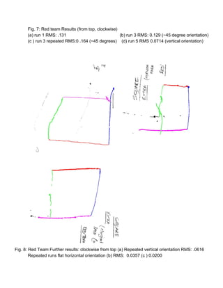
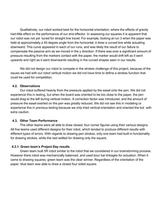
- 13. Fig.╠²7:╠²Red╠²team╠²Results╠²(from╠²top,╠²clockwise)╠²╠² (a)╠²run╠²1╠²RMS:╠².131 ╠² (b)╠²run╠²3╠²RMS:╠²0.129╠²(~45╠²degree╠²orientation)╠² (c╠²)╠²run╠²3╠²repeated╠²RMS:0╠².164╠²(~45╠²degrees)╠²╠²╠²╠²(d)╠²run╠²5╠²RMS╠²0.0714╠²(vertical╠²orientation)╠² ╠² ╠² ╠² ╠² ╠² Fig.╠²8:╠²Red╠²Team╠²Further╠²results:╠²clockwise╠²from╠²top╠²(a)╠²Repeated╠²vertical╠²orientation╠²RMS:╠².0616╠²╠² Repeated╠²runs╠²flat╠²horizontal╠²orientation╠²(b)╠²RMS:╠²╠²0.0357╠²(c╠²)╠²0.0200╠²
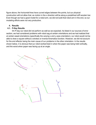
- 17. ╠² ╠² 4.4. Discussion╠² 4.4.1. Mechanical╠²Design╠² One╠²area╠²where╠²our╠²mechanical╠²design╠²could╠²be╠²improved,╠²is╠²in╠²the╠²x╠²direction╠²lever╠²arm.╠²The╠² current╠²lever╠²arm╠²made╠²out╠²of╠²foam╠²core╠²was╠²only╠²connected╠²by╠²a╠²single╠²bolt,╠²and╠²therefore╠²not╠²very╠² rigid.╠²The╠²joint╠²had╠²a╠²lot╠²of╠²give,╠²and╠²for╠²a╠²given╠²x╠²position╠²of╠²the╠²end╠²effector╠²there╠²was╠²a╠²range╠²of╠²x╠² servo╠²angles╠²(up╠²to╠²several╠²degrees)╠²that╠²would╠²result╠²in╠²the╠²same╠²x╠²position.╠²Therefore╠²small╠² changes╠²in╠²the╠²angle╠²of╠²the╠²x╠²position╠²servo╠²did╠²not╠²result╠²in╠²any╠²motion╠²of╠²the╠²end╠²effector.╠²This╠² limited╠²the╠²precision╠²of╠²the╠²end╠²effector╠²in╠²the╠²x╠²direction.╠²If╠²we╠²improved╠²the╠²joint╠²by╠²adding╠²additional╠² bolts╠²and╠²adding╠²more╠²foam╠²core╠²layers╠²to╠²the╠²joint╠²to╠²increase╠²the╠²grip╠²the╠²bolts╠²would╠²have.╠² ╠² Additionally╠²the╠²location╠²of╠²the╠²servo╠²itself╠²could╠²be╠²optimized.╠²In╠²the╠²current╠²configuration╠²the╠² linkage╠²arms╠²are╠²much╠²longer╠²than╠²strictly╠²needed╠²to╠²provide╠²a╠²full╠²range╠²of╠²motion╠²on╠²the╠²x╠²axis.╠²This╠² is╠²due╠²to╠²the╠²servo╠²being╠²mounted╠²so╠²low,╠²relative╠²to╠²the╠²cartesian╠²frame╠²and╠²top╠²of╠²the╠²pivot╠²servo.╠² By╠²raising╠²the╠²height╠²of╠²the╠²servo,╠²the╠²length╠²of╠²that╠²linkage╠²could╠²be╠²greatly╠²reduced,╠²thereby╠² reducing╠²the╠²effects╠²of╠²servo╠²error╠²on╠²x╠²coordinate╠²position.╠² ╠² The╠²inner╠²and╠²outer╠²guides╠²for╠²the╠²slider╠²support╠²rod╠²were╠²an╠²ad┬Łhoc╠²construction╠²that╠²could╠²be╠² greatly╠²improved╠²upon.╠²Gross╠²manufacturing╠²defects╠²in╠²these╠²pieces╠²led╠²to╠²uneven╠²vertical╠²motion╠²of╠² the╠²slider╠²support╠²rod.╠²Vertical╠²motion╠²could╠²also╠²be╠²aided╠²by╠²using╠²a╠²screw╠²with╠²a╠²lower╠²pitch.╠²The╠² lead╠²screw╠²we╠²used╠²required╠²20╠²revolutions╠²per╠²inch╠²of╠²displacement.╠²This╠²made╠²a╠²painfully╠²slow╠² robot╠²and╠²made╠²it╠²difficult╠²to╠²track╠²vertical╠²movement,╠²as╠²the╠²servos╠²needed╠²to╠²be╠²run╠²at╠²full╠²speed.╠² ╠² 4.4.2. Software╠² Our╠²software╠²had╠²features╠²which╠²were╠²underdeveloped╠²and╠²thus╠²not╠²used╠²at╠²P┬ŁDay.╠²This╠² prevented╠²us╠²from╠²trying╠²the╠²stroke╠²challenge╠²even╠²though╠²we╠²had╠²written╠²software╠²for╠²it.╠²Our╠² correction╠²efforts╠²worked╠²well╠²in╠²keeping╠²our╠²straight╠²lines╠²drawn,╠²but╠²we╠²could╠²have╠²done╠²more╠²to╠² mitigate╠²and╠²predict╠²the╠²effect╠²of╠²applied╠²pressure╠²on╠²the╠²pen╠²from╠²a╠²software╠²perspective.╠²Reducing╠² the╠²speed╠²of╠²the╠²servo╠²motion╠²had╠²a╠²very╠²good╠²effect╠²on╠²the╠²response╠²to╠²the╠²midi╠²board,╠²and╠²no╠² additional╠²filtering╠²should╠²be╠²necessary.╠² There╠²is╠²much╠²more╠²work╠²needed╠²to╠²be╠²done╠²on╠²the╠²software.╠²Stroke╠²following╠²should╠²be╠² better╠²tested.╠²The╠²framework╠²has╠²been╠²made,╠²but╠²since╠²drawing╠²a╠²square╠²was╠²the╠²main╠²requirement╠² of╠²the╠²robot,╠²a╠²lot╠²of╠²effort╠²was╠²spent╠²in╠²making╠²sure╠²that╠²it╠²would╠²draw╠²a╠²square,╠²and╠²not╠²much╠²on╠²the╠² following╠²of╠²arbitrary╠²points.╠²Much╠²more╠²testing╠²should╠²be╠²done╠²to╠²make╠²sure╠²that╠²the╠²proposed╠² function╠²in╠²RedArmDriver.py╠²will╠²go╠²between╠²poits.╠²The╠²inverse╠²kinematics╠²function╠²must╠²also╠²be╠² implemented╠²to╠²convert╠²between╠²paper╠²coordinates╠²and╠²robot╠²arm╠²angles.╠²It╠²was╠²deemed╠² unnecessary╠²for╠²the╠²drawing╠²of╠²the╠²square╠²as╠²we╠²could╠²hard┬Łcode╠²the╠²four╠²corners╠²in╠²the╠²x┬Ły╠²robot╠² plane╠²and╠²orient╠²our╠²robot╠²accordingly.╠² The╠²moveTogether╠²function╠²in╠²the╠²driver╠²file╠²has╠²shown╠²good╠²diagonal╠²motion╠²in╠²testing,╠²so╠² fully╠²testing╠²that╠²with╠²added╠²pen╠²pressure╠²and╠²creating╠²an╠²additional╠²function╠²to╠²read╠²the╠²vector╠²of╠²
- 19. ╠² 5. References╠² [1]╠²╠²╠²╠²╠²http://www.societyofrobots.com/robot_arm_tutorial.shtml#joint_force╠² additionally,╠²see╠²references╠²in╠²the╠²presentations╠² ╠² 6. Appendix╠² 7.1 ╠²Source╠²Code:╠²https://wiki.eecs.umich.edu/hrb/index.php/File:Red_2_Source_Code.py╠²╠² 7.2. ╠²CAD╠²Model:╠² https://drive.google.com/folderview?id=0Bw2WF0CVsfPnNldDblNQUE5FYVk&usp=sharing╠²╠² 7.3 ╠²Robot╠²Video:╠²https://www.youtube.com/watch?v=2r7dksC┬ŁIGA╠²╠² 7.4 Modeling╠²code:╠²https://wiki.eecs.umich.edu/hrb/index.php/File:RedArmModel.txt╠²╠²

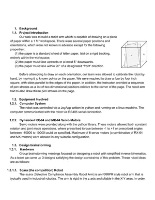
![to╠²meet╠²the╠²design╠²constraints╠²of╠²the╠²project,╠²an╠²additional╠²axis╠²of╠²rotation╠²would╠²have╠²to╠²be╠²
implemented╠²in╠²order╠²to╠²control╠²the╠²orientation╠²of╠²the╠²end╠²effector.╠²╠²
The╠²design╠²would╠²allow╠²us╠²to╠²reach╠²every╠²point╠²and╠²pen╠²orientation╠²in╠²the╠²workspace,╠²but╠²at╠²
the╠²expense╠²of╠²difficult╠²inverse╠²kinematics╠²and╠²the╠²mechanical╠²design╠²challenge╠²of╠²correctly╠²balancing╠²
the╠²hanging╠²servos.╠²╠²
╠²
╠²
╠² ╠²
╠²╠²╠²╠²╠²╠²Fig.╠²1:╠²SCARA╠²robot╠²arm╠²╠²[1]╠²
╠²
╠²
1.3.1.2. R┬Ł4╠²Robot╠²╠²
Similarly,╠²to╠²the╠²SCARA╠²robot,╠²the╠²R┬Ł4╠²robot╠²was╠²an╠²assemblage╠²of╠²4╠²revolute╠²joints╠²that╠²could╠²
reach╠²all╠²of╠²the╠²points╠²and╠²orientation╠²in╠²the╠²robot╠²workspace.╠²The╠²design╠²was╠²better╠²than╠²the╠²scara╠²
robot,╠²in╠²that╠²the╠²inverse╠²kinematics╠²calculations╠²required╠²for╠²the╠²design╠²would╠²be╠²simplified,╠²however╠²
this╠²design╠²would╠²still╠²be╠²very╠²hard╠²to╠²implement╠²from╠²a╠²mechanical╠²perspective.╠²We╠²anticipated╠²
issues╠²with╠²arm╠²sag╠²and╠²torque╠²requirements╠²of╠²the╠²servo╠²motors╠²that╠²were╠²a╠²result╠²of╠²the╠²robot╠²arms╠²
hanging╠²servos.╠²
╠²╠²
╠²
╠²
╠²
╠²
╠²
╠²
╠²
╠²
╠²
╠²
Fig.╠²2:╠²CAD╠²model╠²of╠²a╠²R┬Ł4╠²bot╠²controlled╠²with╠²4╠²revolute╠²joints╠²
╠²
╠²](https://image.slidesharecdn.com/b472a9e0-8d07-4473-8f75-8edcadc20c19-150111231851-conversion-gate01/85/Hands-on-Robotics_Robotic-Arm-4-320.jpg)


![╠²
5. References╠²
[1]╠²╠²╠²╠²╠²http://www.societyofrobots.com/robot_arm_tutorial.shtml#joint_force╠²
additionally,╠²see╠²references╠²in╠²the╠²presentations╠²
╠²
6. Appendix╠²
7.1 ╠²Source╠²Code:╠²https://wiki.eecs.umich.edu/hrb/index.php/File:Red_2_Source_Code.py╠²╠²
7.2. ╠²CAD╠²Model:╠²
https://drive.google.com/folderview?id=0Bw2WF0CVsfPnNldDblNQUE5FYVk&usp=sharing╠²╠²
7.3 ╠²Robot╠²Video:╠²https://www.youtube.com/watch?v=2r7dksC┬ŁIGA╠²╠²
7.4 Modeling╠²code:╠²https://wiki.eecs.umich.edu/hrb/index.php/File:RedArmModel.txt╠²╠²](https://image.slidesharecdn.com/b472a9e0-8d07-4473-8f75-8edcadc20c19-150111231851-conversion-gate01/85/Hands-on-Robotics_Robotic-Arm-19-320.jpg)