Finite Element Method
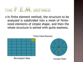
- 2. The F.E.M. DefinedIn finite element method, the structure to be analyzed is subdivided into a mesh of finite-sized elements of simple shape, and then the whole structure is solved with quite easiness.Finite Sized ElementRectangular BodyCircular Plate
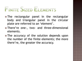
- 3. Finite Sized ElementsThe rectangular panel in the rectangular body and triangular panel in the circular plate are referred to an ‘element’.There’re one-, two- and three-dimensional elements.The accuracy of the solution depends upon the number of the finite elements; the more there’re, the greater the accuracy.
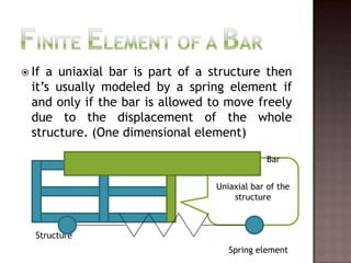
- 4. Finite Element of a BarIf a uniaxial bar is part of a structure then it’s usually modeled by a spring element if and only if the bar is allowed to move freely due to the displacement of the whole structure. (One dimensional element)BarUniaxial bar of the structureStructureSpring element
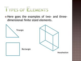
- 5. Types of ElementsHere goes the examples of two- and three-dimensional finite sized elements.TriangleRectangleHexahedron
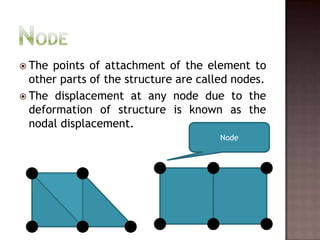
- 6. NodeThe points of attachment of the element to other parts of the structure are called nodes.The displacement at any node due to the deformation of structure is known as the nodal displacement.Node
- 7. Why F.E.M.?Simple trusses can be solved by just using the equilibrium equations. But for the complex shapes and frameworks like a circular plate, equilibrium equations can no longer be applied as the plate is an elastic continuum not the beams or bars as the case of normal trusses.
- 8. Hence, metal plate is divided into finite subdivisions (elements) and each element is treated as the beam or bar. And now stress distribution at any part can be determined accurately.Simple Bar AnalysisBy The Help Of FEM
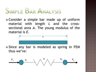
- 9. Simple Bar AnalysisConsider a simple bar made up of uniform material with length L and the cross-sectional area A. The young modulus of the material is E.Since any bar is modeled as spring in FEM thus we’ve:Lx2kF1F2x1
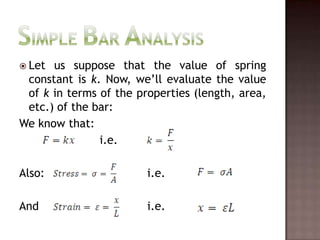
- 10. Let us suppose that the value of spring constant is k. Now, we’ll evaluate the value of k in terms of the properties (length, area, etc.) of the bar:We know that: i.e. Also: i.e.And i.e.Simple Bar Analysis
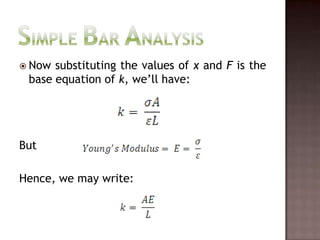
- 11. Now substituting the values of x and F is the base equation of k, we’ll have:ButHence, we may write:Simple Bar Analysis
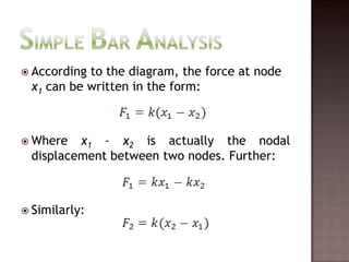
- 12. Simple Bar AnalysisAccording to the diagram, the force at node x1 can be written in the form:Where x1 – x2is actually the nodal displacement between two nodes. Further:Similarly:
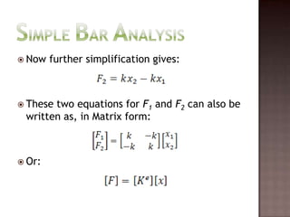
- 13. Simple Bar AnalysisNow further simplification gives:These two equations for F1 and F2 can also be written as, in Matrix form:Or:
- 14. Simple Bar AnalysisHere Ke is known as the Stiffness Matrix. So a uniform material framework of bars, the value of the stiffness matrix would remain the same for all the elements of bars in the FEM structure.
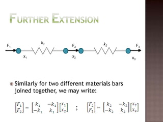
- 15. Similarly for two different materials bars joined together, we may write: ;Further Extensionk1k2F1F2F3x1x2x3
- 16. Numerical ProblemWith The Help Of FEM Analysis For Bars
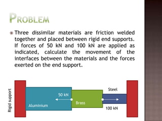
- 17. ProblemThree dissimilar materials are friction welded together and placed between rigid end supports. If forces of 50 kN and 100 kN are applied as indicated, calculate the movement of the interfaces between the materials and the forces exerted on the end support.SteelRigid support50 kNBrassAluminium100 kN
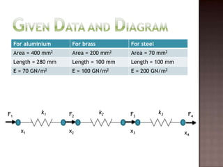
- 18. Given Data And Diagramk1k2k3F1F2F3F4x1x2x3x4
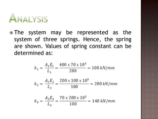
- 19. The system may be represented as the system of three springs. Hence, the spring are shown. Values of spring constant can be determined as:Analysis
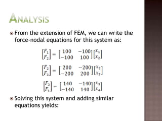
- 20. From the extension of FEM, we can write the force-nodal equations for this system as:Solving this system and adding similar equations yields:Analysis
- 21. Now:From these equations we can easily determine the unknowns, but we’ll have to apply the boundary conditions first.Analysis
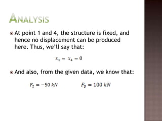
- 22. At point 1 and 4, the structure is fixed, and hence no displacement can be produced here. Thus, we’ll say that:And also, from the given data, we know that:Analysis
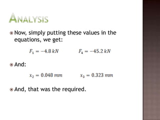
- 23. Now, simply putting these values in the equations, we get:And:And, that was the required.Analysis
- 24. The Last WordComplex Structure Analysis
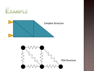
- 25. Complex StructuresComplex structures which contain the material continuum, are subdivided into the elements and are analyzed on the computers. Software packages are available for the determination of the Stiffness matrix of those structures.Some software packages also allow virtual subdivision on the computer as well i.e. computer automatically analyzes the shape, and gives the stress-strain values at any point of the structure.
- 27. Inclined BarsInclined bars are always analyzed by resolving them into their x- and y-components. The value of the inclined angle is always known and then the components are evaluated.Three-dimensional structures involve three dimensional elements i.e. elements with three dimensions (length, width, thickness).
- 28. ImportanceFEM has become very familiar in subdivision of continuum. It gives reliable and accurate results if the number of elements are kept greater.Modern computer technology had helped this analysis to be very easy and less time consuming.Large structures under loadings are now easily solved and stresses on each and every part are now being determined.
- 29. Thank YouVery MuchSheikh Haris Zia08-ME-39Ibrahim Azhar08-ME-53Muhammad Haris08-ME-69
Editor's Notes
- #2: This is the first slide, shows only the presentation title and the subtitle with high texture animations.
- #3: Defines the FEM. Show the physical meaning of the FEM. Compares two geometries; rectangular and circular.
- #4: Defines the Finite Sized Elements, and their characteristics.
- #5: If a bar is to be modeled, then it would be replaced by a spring in FEM. How? Well explained with animation in this slide.
- #6: Displays some types of elements that are also being used in FEM.
- #7: Defines the node as it’s necessary to be defined right here.
- #8: Why there is a need to implement the method of F.E.M. which is also quite difficult from the other methods?
- #9: ÔÅä ÔÅä
- #10: Analysis for the simple bar would start here.
- #11: Derivation of the spring constant has been started.
- #12: Derivation for the spring constant has been completed.
- #13: Analysis goes here, x1-x2 is the nodal displacement b/w two nodes 1 and 2.
- #14: Continued.
- #15: Continued.
- #16: Continued.
- #17: ÔÅä ÔÅä
- #18: Problem statement.
- #19: Given data and free body diagram according to the FEM.
- #20: Determination of spring constant k.
- #21: Stiffness matrix.
- #22: Equations.
- #23: Boundary conditions and given data.
- #24: Required answer.
- #25: ÔÅä ÔÅä
- #26: Complex structures.
- #27: Example of Complex structure.
- #28: How to solve the inclined bars?
- #29: What is the importance of the FEM in scientific life for the beam analysis?
- #30: Bya Bya … Allah Hafiz ... Jaan Chhoti … !


