Counters
- 1. Counters design in Cadence By Gonugunta saiphani kumar Roll num:1421908 M.tech VLSI 2nd sem NIT jalandhar 1
- 2. Counters ïĩ The major work of counter is counting of time / frequency electronic pulse ïĩ Applications: Alarm clock Set an AC/TV timer Set a timer for taking picture Flashing indicator lights of your vehicle Counting the time allotted for a "process" The finite state machines In various ADC Communication (serial to parallel ,parallel to serial) 2
- 3. Real time applications Shipment quantities are counted to control the conveyor line flow. 3
- 4. Incoming and outgoing cars are counted to switch the FULL and VACANT signs. 4
- 5. Rotary encoder signals are counted to control a valve aperture. 5
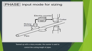
- 6. Teamed up with a rotary encoder, the counter is used to control the cutting length of pipes. 6
- 7. Labeled cans alone are counted up. Rejected cans are not counted. 7
- 8. Medicine tablets are packed in specified quantities. 8
- 9. Printed matter is counted to package a specified number of copies. 9
- 10. Extra leader sheet that is now wound is counted by a rotary encoder and a color detecting sensor. 10
- 11. Incoming and outgoing parts are counted to keep parts feeders well-stocked. 11
- 12. Types of counters Asynchronous/Ripple counters: counter that is formed from n cascaded flip-flops. The clock input to each of the individual flip-flops, with the exception of the first, is taken from the output of the preceding one. Ex: Binary up counter, Binary down counter, Binary up/down counter, Mod-N counter, BCD counter(Mod-10) synchronous counters: A counter consisting of an interconnected series of flip-flops in which all the flip-flop outputs change state at the same instant, normally on application of a pulse at the counter input Ex: Binary up counter, Binary down counter, Binary up/down counter, Mod-N counter, BCD counter(Mod-10), Ring counter, Johnson counter, Binary presettable counter 12
- 14. Positive edge triggered D-FF 14
- 18. Properties of Johnson counter ïĩ Simulator--Cadence ïĩ Technology--180nm ïĩ W/L of pmos = 600nm/180nm ïĩ W/L of nmos = 240nm/180nm ïĩ No. of transistors = 104 ïĩ Clock range 1.8v - 0v ïĩ Clock ON time =10nnm ïĩ Clock time period = 25nm ïĩ Rise & fall time = 1fs ïĩ VDD = 1.8V ïĩ GND = 0v 18
- 19. Results of Johnson counter ïĩ Avg.Power consumption = 6.10Ξw ïĩ High to low delay (at every stage) = 219.5ps ïĩ Low to high delay(at every stage) = 136ps ïĩ Max. frequency of operation = 7.35 Ghz 19
- 21. Negative edge triggered j-k FF 21
- 24. Delay at each stage 24
- 26. Properties of up counter ïĩ Simulator--Cadence ïĩ Technology--180nm ïĩ W/L of pmos = 600nm/180nm ïĩ W/L of nmos = 240nm/180nm ïĩ No. of transistors = 152 ïĩ Clock range 1.8v - 0v ïĩ Clock ON time =10nnm ïĩ Clock time period = 20nm ïĩ Rise & fall time = 1fs ïĩ VDD = 1.8V ïĩ GND = 0v 26
- 27. Results of up counter ïĩ Avg. power consumption = 11.3Ξw ïĩ Delay at first stage = 176.1ps ïĩ Delay at second stage = 467.5ps ïĩ Delay at third stage = 762.1ps ïĩ Delay at fourth stage = 1.025ns ïĩ Max. frequency of operation = 5.67Ghz 27
- 28. References ïĩ www.wikipedia.org/counters. ïĩ http://wearcam.org/lectureflipflop. ïĩ http://smartsim.org.uk/examples projects. ïĩ www3.panasonic.biz /applications of counters 28
- 29. 29


