


Ultrasound artifacts
- 1. * Ansari Abdulla BSc MIT 6th Sem.
- 2. * *An ultrasound artifact is a structure in an image which does not directly similiar with actual tissue being scanned. *Artifact assumes different forms including : • Structures in the image that are not actually present • Objects that should be represented but are missing from the image. • Structures which are misregistered on the image.
- 3. 1. REVERBERATION 2. ACOUSTIC SHADOWING 3. ACOUSTIC ENHANCEMENT 4. EDGE SHADOWING 5. BEAM WIDTH ARTIFACT 6. SLICE THICKNESS ARTIFACT 7. SIDE LOBE ARTIFACT 8. MIROR IMAGE 9. DOUBLE IMAGE 10.EQUIPMENT-GENERATED ARTIFACT 11.REFRACTION ARTIFACT
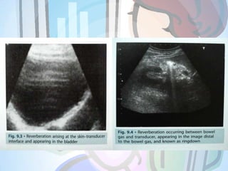
- 4. • This is the production of false echoes due to repeated reflections between two interfaces with a high acoustic impedance mismatch. • The echo from the interface is received by the transducer and displayed on the image. • Some of the energy in the returned echo is reflected at the transducer face, and return to the reflecting interface as if it was a weak transmitted pulse, returning as a second echo. • As the time taken for the second echo to arrive is twice that taken by the depth. *
- 5. • This sequence of reflection and transmission can occur many times, with the third echo taking three times as long to return to the transducer and being displayed at three times the depth, and so on. • The reverberation echoes will be equally spaced because the time for each additional echo is multiple of the time of return of the first echo. • These reverberation echoes will be strong because of the high acoustic mismatch.
- 6. This artifact will be seen at the skin-transducer interface and behind bowel gas. Rectification: • Increase the amount of gel used. • Use a stand-off pad. • Reduce the gain. • Move the position of the transducer.
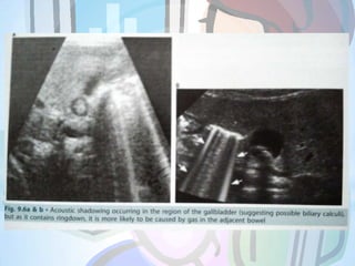
- 8. • This appears as an area of low amplitude echoes behind an area of strongly attenuating tissue. • It is caused by severe attenuation of the beam at an interface, resulting in very little sound being transmitted beyond. • The attenuation can be due to either absorption or reflection of the sound waves, or a combination of the two. • Acoustic shadowing will occur at interfaces with large acoustic mismatch such as: Soft tissue and gas Soft tissue and bone or calculus *
- 11. • This artifact appears as a localized area of increased echo amplitude behind an area of low attenuation. • On a scan it will appears as an area of increased brightness, and can commonly be seen distal to fluid-filled structures such as the urinary bladder, GB or a cyst. • The artifact arises due to the application of the time-gain compensation(TGC) to areas of low attenuating structures such as fluid. • It is caused by the low level of attenuation of the beam as it passes through fluid relative to the greater attenuation of the beam in the adjacent more solid tissue. *
- 12. • This artifact can often be an useful diagnostic aid, particularly when scanning a soft-tissue mass or cyst containing low level echoes. • These echoes may often cause the structure to disappear in the image as it blend into the surrounding echo pattern.
- 13. • A combination of refraction and reflection occurring at the edges of rounded structures will result in edge shadowing artifact. • It arises due to refraction of the beam caused by both the curvature of the rounded edges and difference in speed of two materials. • When the ultrasound beam reaches the rounded edge of a structure, reflection will occur, with an angle of incidence equal to the angle of reflection. • The outer part of the beam will be totally reflected, but the reminder of the beam passes through the rounded structure and is refracted. *
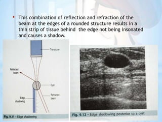
- 14. • This combination of reflection and refraction of the beam at the edges of a rounded structure results in a thin strip of tissue behind the edge not being insonated and causes a shadow.
- 15. • This artifact can be demonstrated by scanning a point reflector in a phantom, where the display will clearly portray this as a line. • During routine scanning, the artifact can be seen when spurious echoes are displayed in an echo-free area. • Correct positioning of the focal zone will help to reduce this artifact. • The focal zone is controlled by electronically narrowing the beam *
- 17. • These occurs due to the thickness of the beam, and are similar to beam width artifacts. • These artifacts will typically be seen in transverse views of the urinary bladder when structures adjacent to the slice through the bladder being scanned will be incorporated into the image. • These echoes are then displayed as if they were arising from within the bladder. • Although the appearance of this artifact is similar to the beam width artifact, the differentiating factors is that the reflector causing the slice thickness artifact will not be seen on the display. *
- 18. • This artifact is a result of inherent characteristics of the transducer, and apart from trying a different transducer, cannot be eliminated.
- 19. • The energy within the ultrasound beam exists as several side lobes radiating at a number of angles from a central lobe. • Echoes are generated by these side lobes in addition to the main lobe, but all the returning echoes are assumed by the transducer to have arisen from the central axis of the main lobe. • Side lobe echoes will therefore be misregistered in the display. • This artifact can often be seen in area such as the urinary bladder and may also arise within a cyst. *
- 21. • These artifacts results in a mirror image of a structure occurring in an ultrasound display. • They arise due to specular reflection of the beam at a large smooth interface. • An area close to a specular reflector will be imaged twice, once by the original ultrasound beam and once by the beam after it has reflected off the specular reflector. • Mirror image artifacts are most commonly seen where there is a large acoustic mismatch, such as a fluid-air interface. *
- 22. • Typically this artifact can occur during the scanning of a full bladder, when air in the rectum behind the bladder act as specular reflector and mirror image of the bladder is displayed posteriorly. • It will then have the appearance of a large cyst behind the bladder. • It can also be seen when scanning the liver, and the diaphragm act as a specular reflector.
- 24. • This image is caused by refraction of the beam and may occur in areas such as the rectus abdominis muscle on the anterior abdominal wall. • In the transverse plane the edges of the muscle act as a lens and the ultrasound beam to be refracted and this causes the single structure to be interrogated by two separate refracted beams. • Two sets of echoes will therefore be returned and these will cause display of two structures in the image. *
- 25. This results in, for example, two images of the transverse aorta side by side in the abdomen.
- 26. • Incorrect use of the equipment controls can lead to artifact appearing. • Misuse of controls such as the gain or TGC can result in echoes being recorded as too bright or too dark. • Care must be taken when setting these controls, to ensure an even brightness throughout the image. • If the dynamic range control is incorrectly set, this can lead to an image which has too much contrast, and result in the loss of subtle echo information. *
- 27. • Gain must be in medium level. • Blurring of a moving image can occur if the frame rate is too low or if the persistence is too high. • It is important to ensure that the frame rate is capable of recording a moving structure at the speed. • Use of multiple focal zones can give rise to a prominent banding effect within the image.
- 29. * • The refraction is the change of the sound direction on passing from one medium to another. • In ultrasound, refraction is due to sound velocity mismatches combines with oblique angles of incidence, most commonly with convex scanheads. • When the ultrasound wave crosses at an oblique angle the interface of two materials, through which the waves propagate at different velocities, refraction occurs, caused by bending of the wave beam. • Refraction artifact cause spatial distortion and loss of resolution in the image.