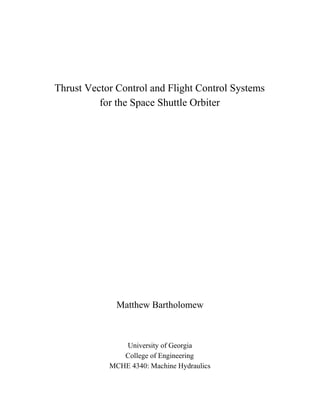
![Figure 2.​ A view of the TVC system on an SRB engine.
Table 1, below, identifies characteristics of the main engine actuators. As you can see, the top
main engine required a larger pitch actuator. Although the pitch actuator is larger, all three yaw actuators
are the same size. I couldn’t find relevant information that definitively states why this actuator is larger,
but it seems reasonable to believe that the upper engine must experience greater reaction forces during
pitch correction procedures and that the use of the larger actuator was to lower the overall system
pressure.
Table 1.​ SSME TVC Actuator Characteristics
Upper Pitch Actuator Lower Pitch Actuator Yaw Actuators
Piston Area [in​2​
] 24.8 20 20
Stroke Length [in] 10.8 10.8 8.8
Flow Rate [gpm] 50 45 45
Weight [lbs] 265 245 240
After re-entering the atmosphere the shuttle operated similar to an airplane with a Flight Control
System; including elevons, body flap, and rudder. In addition, the shuttle had a speed break function
whereby the rudder could split in half and flare to each side, slowing the vehicle. Each of these systems
had separate hydraulic systems that were actuated via fly-by-wire controls (O’Brien, 2501). A schematic
of the system is available below in Figure 3.](https://image.slidesharecdn.com/hydraulicspaper-190523222248/85/Thrust-Vector-Control-and-Flight-Control-Systems-for-the-Space-Shuttle-Orbiter-3-320.jpg)

![The total Space Shuttle Hydraulic system is actually composed of 3 independent systems, each
complete with pump, reservoir, accumulator, filters, control valves, heat exchanger, circulation pump, and
electrical heaters (​Hydraulic System​). The system utilizes MIL-H-83282 fluid due to “compatibility with
most materials that are used in the vehicle and hydraulic system, lower density than oronite, fire resistant
qualities determined by hot manifold, high-pressure spray, low-pressure spray, Navy six-wick, … can
cover tests, and adequate high temperature characteristics” (O’Brien, 2502). The system utilizes both
flexible and rigid tubing. The flexible tubing is Teflon-lined stainless steel and the rigid tubing is
titanium-based (O’Brien, 2503). The system also utilizes some aluminum rigid tubing for return lines not
subject to harsh conditions. The seals used in the system are made of Viton E60C, due to its compatibility
with the fluid as well as ability to withstand high temperatures, and backup seals are made of a Teflon
compound (O’Brien, 2503).
The hydraulic system utilizes variable displacement pumps that operate at 3,900 rpm and between
2,900 and 3,100 psi (​Hydraulic Systems​). The filters entering the system filter to 5 micron and the filters
exiting to the reservoir filter to 15 micron. The filter system also contains a pressure-relief valve which
dumps fluid back into the reservoir should the supply line pressure exceed 3,850 psig (​Hydraulic System​).
The Auxiliary Power Units (APUs) are started 5 minutes before lift off and provide shaft power to drive
the hydraulic pumps. These pumps in turn position the SSMEs, propellant valves, and aerosurfaces for
liftoff conditions. If the systems do not achieve 2,800 psig by 4 minutes to liftoff then the launch
sequence is aborted (​Hydraulic System​). The hydraulic systems operate redundantly on a
fail-operational/fail -safe method. This means that if system 1 fails then systems 2 and 3 can still perform
the action, and if all 3 systems fail then fail-safe actions will be performed so that way the shuttle can
safely return (O’Brien, 2491).
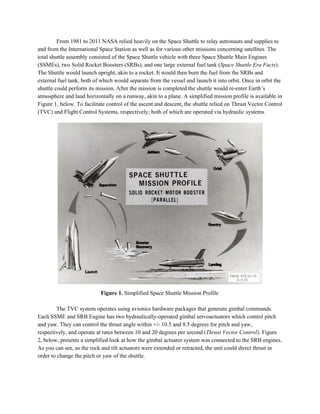
Knowing the operational pressure of the system as 3,000 psi, the piston areas of the cylinders, and
the flow rate for each cylinder presented in Table 1, we can calculate the force during yaw and pitch
actuation as well as the cylinder extension speed and output horsepower. The relevant data and results are
presented in Table 2, below, with the calculated values in bold. In order to perform these calculations we
assumed that the cylinder was 100% efficient.
Table 2.​ Calculated Values of TVC Cylinder Force, Extension Speed, and Horsepower
Upper Pitch Actuation Lower Pitch Actuation Yaw Actuation
System Pressure [psi] 3,000 3,000 3,000
Piston Area [in​2​
] 24.8 20 20
Flow Rate [gpm] 50 45 45
Force [lbf] 74,400 60,000 60,000
Cylinder Extension
Speed [in/min]
465.7 519.8 519.8](https://image.slidesharecdn.com/hydraulicspaper-190523222248/85/Thrust-Vector-Control-and-Flight-Control-Systems-for-the-Space-Shuttle-Orbiter-5-320.jpg)
![Cylinder Extension
Speed [ft/s]
0.6468 0.7219 0.7219
Cylinder Horsepower
[HP]
87.49 78.75 78.75
Further, if we assume that one main TVC pump operates at 140 gpm, being the max required flow
rate for pitch actuation, then we can calculate the average pump displacement by modeling the pump as a
fixed-displacement pump. Relevant values and calculations are presented in Table 3, below.
Table 3.​ Average Pump Displacement Calculation
Flow Rate [GPM] Drive Speed [RPM] Pump Displacement [in​3​
/rev]
140 3900 8.29](https://image.slidesharecdn.com/hydraulicspaper-190523222248/85/Thrust-Vector-Control-and-Flight-Control-Systems-for-the-Space-Shuttle-Orbiter-6-320.jpg)
Thrust Vector Control and Flight Control Systems for the Space Shuttle Orbiter
- 1. Thrust Vector Control and Flight Control Systems for the Space Shuttle Orbiter Matthew Bartholomew University of Georgia College of Engineering MCHE 4340: Machine Hydraulics
- 2. From 1981 to 2011 NASA relied heavily on the Space Shuttle to relay astronauts and supplies to and from the International Space Station as well as for various other missions concerning satellites. The total shuttle assembly consisted of the Space Shuttle vehicle with three Space Shuttle Main Engines (SSMEs), two Solid Rocket Boosters (SRBs), and one large external fuel tank (​Space Shuttle Era Facts​). The Shuttle would launch upright, akin to a rocket. It would then burn the fuel from the SRBs and external fuel tank, both of which would separate from the vessel and launch it into orbit. Once in orbit the shuttle could perform its mission. After the mission is completed the shuttle would re-enter Earth’s atmosphere and land horizontally on a runway, akin to a plane. A simplified mission profile is available in Figure 1, below. To facilitate control of the ascent and descent, the shuttle relied on Thrust Vector Control (TVC) and Flight Control Systems, respectively; both of which are operated via hydraulic systems. Figure 1.​ Simplified Space Shuttle Mission Profile The TVC system operates using avionics hardware packages that generate gimbal commands. Each SSME and SRB Engine has two hydraulically-operated gimbal servoactuators which control pitch and yaw. They can control the thrust angle within +/- 10.5 and 8.5 degrees for pitch and yaw, respectively, and operate at rates between 10 and 20 degrees per second (​Thrust Vector Control​). Figure 2, below, presents a simplified look at how the gimbal actuator system was connected to the SRB engines. As you can see, as the rock and tilt actuators were extended or retracted, the unit could direct thrust in order to change the pitch or yaw of the shuttle.
- 3. Figure 2.​ A view of the TVC system on an SRB engine. Table 1, below, identifies characteristics of the main engine actuators. As you can see, the top main engine required a larger pitch actuator. Although the pitch actuator is larger, all three yaw actuators are the same size. I couldn’t find relevant information that definitively states why this actuator is larger, but it seems reasonable to believe that the upper engine must experience greater reaction forces during pitch correction procedures and that the use of the larger actuator was to lower the overall system pressure. Table 1.​ SSME TVC Actuator Characteristics Upper Pitch Actuator Lower Pitch Actuator Yaw Actuators Piston Area [in​2​ ] 24.8 20 20 Stroke Length [in] 10.8 10.8 8.8 Flow Rate [gpm] 50 45 45 Weight [lbs] 265 245 240 After re-entering the atmosphere the shuttle operated similar to an airplane with a Flight Control System; including elevons, body flap, and rudder. In addition, the shuttle had a speed break function whereby the rudder could split in half and flare to each side, slowing the vehicle. Each of these systems had separate hydraulic systems that were actuated via fly-by-wire controls (O’Brien, 2501). A schematic of the system is available below in Figure 3.
- 4. Figure 3.​ Fly-by-Wire Flight Control System of a Space Shuttle In order for the fly-by-wire system to operate, the motion of the controls must first be transmitted to an electrical signal and then the electrical signal must be transmitted back to mechanical motion via the hydraulic system. In the case of the elevons, the mechanical motion is achieved by tandem actuators in each wing. When the pilot moves the controller it causes an output signal from the force deflector. This output signal then goes into the computer system where it is summed with other signals. Next, the computer transmits a signal that controls the servo-actuators. Finally, this motion is sent back to a display in the cockpit which shows the elevon positions (O’Brien, 2501-2502). The other systems operate in a similar fashion. A schematic of a typical aerodynamic actuator is available in Figure 4, below. Figure 4.​ Typical Aerodynamic Actuator Schematic
- 5. The total Space Shuttle Hydraulic system is actually composed of 3 independent systems, each complete with pump, reservoir, accumulator, filters, control valves, heat exchanger, circulation pump, and electrical heaters (​Hydraulic System​). The system utilizes MIL-H-83282 fluid due to “compatibility with most materials that are used in the vehicle and hydraulic system, lower density than oronite, fire resistant qualities determined by hot manifold, high-pressure spray, low-pressure spray, Navy six-wick, … can cover tests, and adequate high temperature characteristics” (O’Brien, 2502). The system utilizes both flexible and rigid tubing. The flexible tubing is Teflon-lined stainless steel and the rigid tubing is titanium-based (O’Brien, 2503). The system also utilizes some aluminum rigid tubing for return lines not subject to harsh conditions. The seals used in the system are made of Viton E60C, due to its compatibility with the fluid as well as ability to withstand high temperatures, and backup seals are made of a Teflon compound (O’Brien, 2503). The hydraulic system utilizes variable displacement pumps that operate at 3,900 rpm and between 2,900 and 3,100 psi (​Hydraulic Systems​). The filters entering the system filter to 5 micron and the filters exiting to the reservoir filter to 15 micron. The filter system also contains a pressure-relief valve which dumps fluid back into the reservoir should the supply line pressure exceed 3,850 psig (​Hydraulic System​). The Auxiliary Power Units (APUs) are started 5 minutes before lift off and provide shaft power to drive the hydraulic pumps. These pumps in turn position the SSMEs, propellant valves, and aerosurfaces for liftoff conditions. If the systems do not achieve 2,800 psig by 4 minutes to liftoff then the launch sequence is aborted (​Hydraulic System​). The hydraulic systems operate redundantly on a fail-operational/fail -safe method. This means that if system 1 fails then systems 2 and 3 can still perform the action, and if all 3 systems fail then fail-safe actions will be performed so that way the shuttle can safely return (O’Brien, 2491). Knowing the operational pressure of the system as 3,000 psi, the piston areas of the cylinders, and the flow rate for each cylinder presented in Table 1, we can calculate the force during yaw and pitch actuation as well as the cylinder extension speed and output horsepower. The relevant data and results are presented in Table 2, below, with the calculated values in bold. In order to perform these calculations we assumed that the cylinder was 100% efficient. Table 2.​ Calculated Values of TVC Cylinder Force, Extension Speed, and Horsepower Upper Pitch Actuation Lower Pitch Actuation Yaw Actuation System Pressure [psi] 3,000 3,000 3,000 Piston Area [in​2​ ] 24.8 20 20 Flow Rate [gpm] 50 45 45 Force [lbf] 74,400 60,000 60,000 Cylinder Extension Speed [in/min] 465.7 519.8 519.8
- 6. Cylinder Extension Speed [ft/s] 0.6468 0.7219 0.7219 Cylinder Horsepower [HP] 87.49 78.75 78.75 Further, if we assume that one main TVC pump operates at 140 gpm, being the max required flow rate for pitch actuation, then we can calculate the average pump displacement by modeling the pump as a fixed-displacement pump. Relevant values and calculations are presented in Table 3, below. Table 3.​ Average Pump Displacement Calculation Flow Rate [GPM] Drive Speed [RPM] Pump Displacement [in​3​ /rev] 140 3900 8.29