


Vice Grip CAD Project
- 1. Vice-Grips Product Dissection Term Project Bartholomew, Matthew Wise, Jacob 8 December 2015
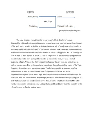
- 2. The first step of this assignment was fairly simple, to choose a product to dissect. Our group chose to use Vice-Grips for two reasons. The first reason is simply that we didn’t know what to use for this project and Ms. Tanner supplied a couple of items to choose from and Vice- Grips sparked our interest. The second reason is that Jacob is a mechanic by trade and I have done a lot of projects before so Vice-Grips are a tool both of us were already familiar with. This style of Vice-Grips is derived from the original Vice-Grips locking pliers. The idea of Vice- Grips was initially thought of by a farmer named William Petersen (Ganzel). Mr. Petersen found “his job would be a lot easier if he had a set of pliers that would clamp down and hold the piece of metal he was working on” (Ganzel). Mr. Petersen eventually developed a working prototype of a product that incorporated both the functions of a vice as well as a set of pliers (Ganzel). Soon, Petersen started selling to other local farmers and opened up a manufacturing plant in 1938(Ganzel). In 1941 Petersen’s plant started fulfilling contracts for both the US and England, which was just what the company needed in order to survive (Ganzel). In 1985 Petersen Manufacturing changed its name to American Tool Companies and in 1993 they obtained IRWIN tool company (IRWIN). Vice-Grips are a simple locking clamp-style mechanism that locks items between the jaws of the tool. The product uses a screw mechanism on the upper handle that pushes on a sliding lever permanently affixed to the lower handle in order to change the distance between the jaws of the tool in the locked position (Appendix A). In order to unlock the jaws, the tool just uses a simple lever mechanism attached to the lower handle. Overall the tool has 10 different parts. The clamp consists of jaw pads, a fixed upper handle/jaw assembly, a moveable lower jaw, a spring, a moveable lower handle, a screw, a release lever, a locking lever, and two different sizes of rivets. The device relies on tension from the spring and screw in order to operate, it also utilizes a simple lever mechanism in order to open back up. The device operates by the user balling their hand into a fist, which pushes the handles together and engages the clamp. In the diagram below you can observe a Black-box diagram that illustrates the general functionality of the Vice-Grips. When the user inputs force and torque by balling their hand into a fist they achieve the outputs of both noise and a clamped work piece.
- 3. INPUTS OUTPUTS Force, torque Noise Vice Grips Work piece Clamped work piece Tightened/loosened work piece The Vice-Grips are riveted together so we weren’t able to do a lot of product disassembly. Ultimately, the most disassembly we were able to do involved taking the spring out of the work piece. In order to do this, we just used a simple pair of needle-nose pliers in order to stretch the spring and take tension off of the handles. After we took it apart we then had to create accurate measurements in order to recreate the tool in AutoCAD (Appendix B). The first step we took in order to draw the tool in AutoCAD was to simply look at it as its various components in order to make it a bit more manageable. In order to measure the parts, we used a pair of electronic calipers. We used the electronic calipers because they are easy and quick to use as well as very accurate. Due to the manufacturing and odd shape of most of the pieces of the Vice- Grips they do not have very precise tolerances. This led us to modify or assume a lot of our measurements in order to ensure that the parts fit together well. Below is a product decomposition diagram for the Vice-Grips. This diagram illustrates the relationship between the individual parts and subassemblies. For example, the Fixed Handle Subassembly is composed of both the fixed handle and an adjustment screw. Also, it can be noted that within the Moveable Handle Subassembly is the Compound Linkage Subassembly and that within this assembly is the release lever as well as the locking lever.
- 4. Overall, the main function of the Vice-Grips is to clamp or tighten two work pieces together. Sub-functions were determined by observing the device in operation and observing the steps taken in order to properly use the device. By doing this we developed a set of critical-path sub-functions that include adjusting the jaws, opening the jaws, clamping the work piece, and tightening/loosening the work piece. The top half of the diagram below also shows a set of secondary functions referred to as all-time functions. These are functions that we observed were maintained at all times and were essential to device operation. These include maintaining jaw separation via the spring, enhance handling comfort, attach spring, connect components, and grasp tool. Vice Grips Fixed Handle Subassembly Fixed Handle Adjusting Screw Rivet Spring Jaw Jaw Pads Rivet MoveableHandle Subassembly MoveableHandle Rivet Compound Linkage Subassembly Release Lever Locking Lever
- 5. Ultimately, Vice-Grips have evolved throughout the years but could still use some product improvement. As mentioned in the introduction the style of Vice-Grips we are using are derived off of the locking plier style developed by Mr. Petersen. The only major change that the original locking pliers developed was that in 1957 Mr. Petersen added the release lever to the tool (Ganzel). The C-style clamp was derived from and operates in the same way as the initial plier style; however, it is not published as to when this occurred. Even though our product is fairly mature we still noted a few improvements that could be made in order for the product to work better, be easier to use, and be more aesthetically pleasing. The first improvement that could be made is to develop a rubberized coating on the handle. This would be molded in order to increase user comfort as well as allowing for a better grip which would increase control of the tool. The second improvement that could be made is a similar rubberized coating in order to cover the jaw pads. Currently, the jaw pads are made of exposed metal, and while this might be fine if you need to quickly clamp two sheets of metal together and weld them or something similar it does little if you need to work or move the part and need a tool with a good grip. For example, if the pads had a rubberized coating you may be able to use it to hold a sheet of metal that you are bending or forging and you won’t have to worry about the metal slipping out of the tool because the rubber had a better grip.
- 6. Works Cited Ganzel, Bill. “Vise Grip.” The Vise Grip Company of Nebraska. Wessels Living History Farm, n.d. Web. 2 Dec. 2015. “IRWIN History.” IRWIN History- IRWIN Tools. IRWIN Tools, n.d. Web. 2 Dec. 2015.
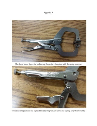
- 7. Appendix A The above image shows the tool during the product dissection with the spring removed. The above image shows one angle of the adjusting/tension screw and locking lever functionality.
- 8. This image is a different angle showing the same screw and lever assembly, this time getting a better view on the channel that the lever slides through. This is a close-up image of the jaws and jaw pads showing how the jaw pads are shaped and riveted onto the jaws so that they are free to swivel.
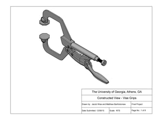
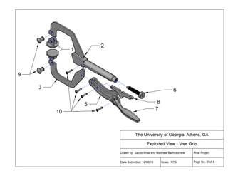
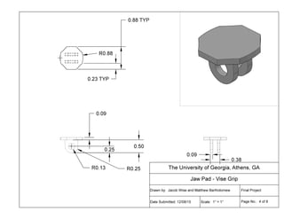
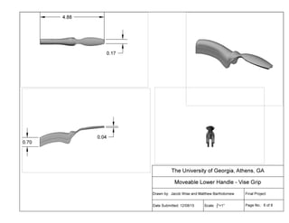
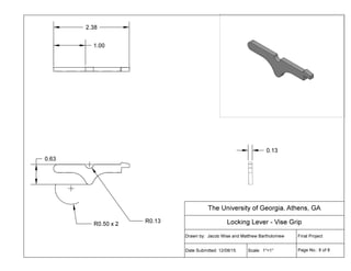
- 9. Appendix B The following pages show the AutoCAD recreations of our Vice Grips. Page 1 depicts a fully assembled and functional model of the Vice Grips. Page 2 features an exploded view of the tool along with a Bill of Materials and leader lines to indicate different parts. The remainder of the pages (3-8) depicts dimensioned 3-View Multiviews of the components. In the order they appear they are: Bolt, Jaw Pad, Fixed Upper Handle Assembly, Moveable Lower Handle, Moveable Lower Jaw, and the Locking Lever.