Hydraulic actuation
âĒ
1 likeâĒ1,106 views

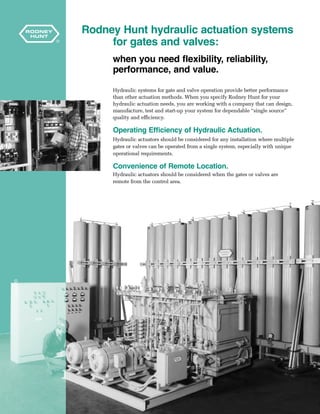
Rodney Hunt provides hydraulic actuation systems for gates and valves that offer several benefits over other actuation methods, including more cost effectiveness, less wear that is ideal for frequent cycling, precise positioning, operation during power failures, and single-source design, manufacture, and start-up. Hydraulic actuation systems provide flexibility in speed control, reliability in hazardous environments, confidence of emergency actuation, and lower maintenance needs for applications with frequent operation or modulation. Rodney Hunt can design, manufacture, test, and start-up hydraulic actuation systems to meet various application requirements.


Hydraulic actuation
- 1. Rodney HuntA GA Industries Company Hydraulic Actuation Systems for Gates and Valves â More cost effective in many applications â Less wear...ideal for frequent cycling â Precise positioning â Operation during power failure â Single-source design, manufacture, start-up (unit responsibility) â High degree of flexibility in speed control Bulletin HAS96
- 2. 2 Rodney Hunt hydraulic actuation systems for gates and valves: when you need flexibility, reliability, performance, and value. Hydraulic systems for gate and valve operation provide better performance than other actuation methods. When you specify Rodney Hunt for your hydraulic actuation needs, you are working with a company that can design, manufacture, test and start-up your system for dependable âsingle sourceâ quality and efficiency. Operating Efficiency of Hydraulic Actuation. Hydraulic actuators should be considered for any installation where multiple gates or valves can be operated from a single system, especially with unique operational requirements. Convenience of Remote Location. Hydraulic actuators should be considered when the gates or valves are remote from the control area.
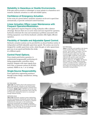
- 3. Reliability in Hazardous or Hostile Environments. If the gate and/or actuator is submerged, or must operate in a hazardous envi- ronment, hydraulic actuation is a safe and reliable option. Confidence of Emergency Actuation. In the event of a power failure, hydraulic actuators can be set to open/close automatically, or provide continued control functions. Linear Actuation Offers Lower Maintenance with Frequent Operation/Modulation. If the application requires frequent cycling, hydraulics offer a distinct advantage. Because there are no screw stems and nuts required for operation, hydraulics eliminate the wear and maintenance problems associated with rotating equipment. Low friction hydraulic cylinders offer highly efficient operation. Flexibility of Variable and Adjustable Speed Control. Hydraulic actuation systems can be provided for an almost limitless variety of independent and field adjustable open/close speeds. The system can even be designed for variable open/close cycles, where the gate or valve opens/closes part way at one speed and finishes the stroke at a different speed. Control Panel Options. From simple push-button operation, to sophisticated programmable positioning uti- lizing programmable controllers where required. Integrate with input signals from level, flow, or pressure sensors (or SCADA systems). NEMA 4, 4x, 7, or 12 ratings. Single-Source Responsibility. From application engineering assistance through system design, manufacture, testing, and start-up. On the cover Upper left: Two Rodney Hunt self-contained sluice gates with hydraulic cylinders in the North System Headworks of the Deer Island primary treatment facil- ity, Boston. Middle right: A SCUBA unit can be used to operate large water and wastewater valves, like this 36â Rotovalve, destined for service in a municipal sewage treatment facility. OPPOSITE PAGE Above left: Hydraulic actuation system engineering includes development of hydraulic power units with programmable controls that can respond to computer instructions for exact gate or valve positioning, continuous monitoring, and emergency operation. Below: The hydraulic power unit for the North River WWTP in New York City. The accumulators provide emergency closure of influent sluice gates. ON THISâPAGE Above: A SCUBA unit installed at the Spring Creek Auxiliary Plant (New York City) to provide âpower failureâ actuation. Unit per- formed 1003 power failure cycles over a 6-month period to obtain New York DEP approval. Left: A hydraulic system used to automatically operate a gate controlling influent water level at the Park Pump Station, Hellertown, PA. Below: The Rodney Hunt complex in Orange, Massachusetts, includes a modern foundry, complete fabri- cation and machining areas, hydraulic sys- tem design and manufacturing areas, and hydrostatic testing facilities.
- 4. 4 Hydraulic actuation is ideal for a range Central Systems â When multiple devices require actuation. â When devices to be operated are in the same facility. â When valving is local, and/or remote. StreamsealÂŪ Butterfly Valves Central System Sluice Gates Crest Gates Rotary Ball or Cone Valves Bonneted Gates
- 5. 5 of applications. Dedicated Systems â When single devices require actuation. â When multiple devices are widely separated. â When the application is critical. SCUBAâĒ Actuators â For small to medium sizes of gates, valves, or other devices. â When space is a premium. â For ease of installation. â Ideal for CSO and retrofit applications. â Perfect for hostile, exposed, or submerged environments. Control Panel/System Gate or Valve Gate Valve SCUBA SCUBA
- 6. 6 Hydraulic Actuation 20QUESTIONS:The following represent 20 of the most commonly asked questions about the hydraulic operation of gates and valves, hydraulic power units and their electrical controls. Please contact Rodney Hunt Company for answers to any other questions you may have. 1. Where should hydraulic actuation be used? Hydraulic actuation should be used for any installations where there are a number of gates or valves that can be operated from a single system; installations where the gates, valves, and actuators must be submerged; and installations where the gates or valves must operate in a power failure or other emergency. Hydraulic actuators are particularly desirable where equipment is to be operated frequently, where loads are high, where the speed of operation is high or must be varied during operation, and where gates or valves are located in a hazardous area requiring explosion-proof and intrinsi- cally safe equipment. 2. How many gates or valves can a single hydraulic system operate? Any number. Practically, the number depends on the sizes of the cylinders, the type of operation, the area available for the system and controls, as well as the dis- tance to the devices being actuated. 3. Can hydraulic cylinders be used for submerged service? Yes. Special rod seals are used to make the cylinders suitable for use under water. The hydraulic fluid lines are brought to the hydraulic system located above the water surface. In drinking water applications, special non-toxic hydraulic fluids can be used. Also, stainless steel components are recommended. This Rodney Hunt hydraulic actuation system operates two 156â x 192â Rodney Hunt crest gates installed at the Deer Island facility in Boston Harbor.
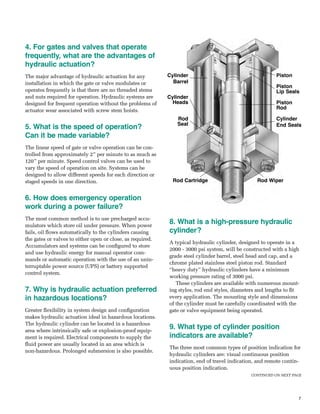
- 7. 7 4. For gates and valves that operate frequently, what are the advantages of hydraulic actuation? The major advantage of hydraulic actuation for any installation in which the gate or valve modulates or operates frequently is that there are no threaded stems and nuts required for operation. Hydraulic systems are designed for frequent operation without the problems of actuator wear associated with screw stem hoists. 5. What is the speed of operation? Can it be made variable? The linear speed of gate or valve operation can be con- trolled from approximately 2â per minute to as much as 120â per minute. Speed control valves can be used to vary the speed of operation on site. Systems can be designed to allow different speeds for each direction or staged speeds in one direction. 6. How does emergency operation work during a power failure? The most common method is to use precharged accu- mulators which store oil under pressure. When power fails, oil flows automatically to the cylinders causing the gates or valves to either open or close, as required. Accumulators and systems can be configured to store and use hydraulic energy for manual operator com- mands or automatic operation with the use of an unin- terruptable power source (UPS) or battery supported control system. 7. Why is hydraulic actuation preferred in hazardous locations? Greater flexibility in system design and configuration makes hydraulic actuation ideal in hazardous locations. The hydraulic cylinder can be located in a hazardous area where intrinsically safe or explosion-proof equip- ment is required. Electrical components to supply the fluid power are usually located in an area which is non-hazardous. Prolonged submersion is also possible. 8. What is a high-pressure hydraulic cylinder? A typical hydraulic cylinder, designed to operate in a 2000 - 3000 psi system, will be constructed with a high grade steel cylinder barrel, steel head and cap, and a chrome plated stainless steel piston rod. Standard âheavy dutyâ hydraulic cylinders have a minimum working pressure rating of 3000 psi. These cylinders are available with numerous mount- ing styles, rod end styles, diameters and lengths to fit every application. The mounting style and dimensions of the cylinder must be carefully coordinated with the gate or valve equipment being operated. 9. What type of cylinder position indicators are available? The three most common types of position indication for hydraulic cylinders are: visual continuous position indication, end of travel indication, and remote contin- uous position indication. CONTINUED ON NEXT PAGE Piston Piston Lip Seals Piston Rod Cylinder End Seals Rod Cartridge Rod Wiper Cylinder Barrel Cylinder Heads Rod Seal
- 8. 8 Visual cylinder position indication is provided by means of a tail rod attached to the cylinder piston. The tail rod will exactly track the piston and gate or valve movements. End of travel indication can be accomplished either by proximity switches mounted in the head and cap of a hydraulic cylinder or by limit switches mounted external to the cylinder body. Proximity switches in the cylinder are recommended as they offer the simplest installation and most reliable operation. In both instanc- es, an electrical contact closure at full cylinder travel can provide end of travel indication by lights installed at any desired location, local or remote. Continuous position indication is generally accom- plished using a linear transducer inserted inside the cylinder. A 4-20 mA signal is generated, corresponding to the position of the piston in the cylinder. 10. What kind of hydraulic fluids are used? Are there options? Typically, a high grade petroleum-based hydraulic oil is used in operating a hydraulic system. There are also standard non-flammable hydraulic fluids available, but they are substantially more expensive. Biodegradable or âfood gradeâ hydraulic fluids are available, and should be considered where the gates or valves are used to control drinking water. However, petroleum-based fluids offer superior operating charac- teristics. 11. Why not use air or water? Both air and water are usually furnished at low pres- sures, in the range of 60 -120 psi. Due to this low pres- sure, all required components and cylinders must be substantially larger than if a high pressure hydraulic fluid system were used. This increases the overall cost of the operating system. Water is also unsuitable at tem- peratures below 32°F. Also, both water and air are corrosive, requiring spe- cial and high cost cylinder and system components. 12. What is recommended system pressure? The generally accepted operating pressure for hydrauli- cally operated gates and valves is 2000 psi. A system pressure of 2000 psi offers a comfortable margin of safe- ty for readily available equipment rated for 3000 psi. The AWWA standard for Power Actuating Devices for Valves and Sluice Gates, AWWA C540, describes hydraulic actuation of valves and sluice gates. The stan- dard covers hydraulic oil cylinders operating up to 2500 psi. The pressure allows the use of standard com- ponents that are suitable for 3000 psi with an adequate factor of safety. It also allows the use of smaller compo- nents than would be possible at lower pressures, thus reducing system costs. Hydraulic systems designed for 2000 psi to 2500 psi operating pressure have been used successfully for many years to operate equipment. A 2000-3000 psi system can be used to operate equipment at lower pressures by the use of pressure reducing valves for that section of the system. 13. What are the basic components of the hydraulic actuation system? Depending upon project requirements, hydraulic sys- tems have a reservoir with the necessary filters, oil filler pipes, oil level sight gauge, a clean-out access, and the motor driven pump or pumps mounted on, or adjacent to, the reservoir. The valving usually consists of a pres- sure relief valve to limit the maximum operating pres- sure of the system; directional control valves that direct the fluid to open or close the gates or valves; speed control valves to control the speed of opening and clos- ing; and pilot-operated check or counterbalance valves to lock the piston in place to prevent drift when the directional control valves are shut off. Many other con- trols â along with an electrical control panel â can be provided as desired or required by the different modes of operation needed. A hand pump can be provided for reduced speed emergency operation when there is a loss of electric power. Hydraulic Actuation 20QUESTIONS CONTINUED
- 9. 9 RESERVOIR CHECK VALVE PRESSURE RELIEF VALVE PRESSURE REDUCING VALVE PILOT OPERATED CHECK VALVE FLOW CONTROL VALVE PRESSURE SWITCH ACCUMULATORDIRECTIONAL CONTROL VALVE PUMP FILTER PRESSURE GAUGE Symbols used on hydraulic schematic diagrams 14. How big are hydraulic power units? Hydraulic power units are designed to be as compact as practical although their size may vary considerably depending on the functional requirements of the sys- tem. A hydraulic power unit designed to operate three (3) 60â x 60â sluice gates may typically have the enve- lope dimensions of 4â wide by 4â deep by 6â high. All necessary valves, motors, electrical controls and the hydraulic reservoir will likely fit within this area. Service access should be provided preferably from three sides. If accumulators are required, they will typically be located integrally or adjacent to the hydraulic power unit, depending on their size. 15. Can the hydraulic system be outside? How far can it be from the equipment? Typically, the equipment operated should be within 300 feet of the power unit. The further away the gates or valves are from the power unit, the larger the intercon- necting piping must be to keep the pressure drop at acceptable levels. Rodney Hunt has supplied hydraulic systems in which the gates were over 500 feet from the hydraulic power unit. Hydraulic systems can be designed for installation outside, but it is preferable to locate the system indoors, or in a weatherproof enclosure. Hydraulic systems oper- ate best when the ambient temperature for the system is between 40° and 100°F. Heaters can be added to heat the oil where the temperature drops below 40°F, and heat exchangers can be used to cool the oil for locations where the temperature exceeds 100°F. The cylinders themselves can be located outside in areas where the temperatures are extreme. 16. What control options are there? Almost any type of operation is available. Control of gates or valves can range from very simple manual operation, using manually operated directional control valves located at the gate or valve, to sophisticated pro- cess controls which automatically position multiple gates or valves to control water level or flow. There are an unlimited number of control conditions, including simple push button operation, remote opera- tion, gate/valve modulation, and automatic emergency or power failure operation. Some of the more complex systems are best operated by programmable controls. Programmable controls provide sophisticated control logic and reduce the space and labor associated with control relays and other devices. Typically, programma- ble controllers are used as the base for the electrical controls because they provide a complete and very flex- ible package for all control logic necessary for varied control applications. Programmable controls have an important advantage in that, should operating condi- tions change at some point, the programmable control- ler can be easily re-programmed to fit new operating conditions. 17. How does the power failure accumulator system work? Are there other power failure options? Accumulators are pressure vessels which store hydrau- lic fluid by compressing an inert gas. In high pressure systems, the gas (normally dry nitrogen) is separated from the hydraulic fluid by either a moveable piston or rubber bladder. In low pressure systems, the gas, typi- cally air, is not isolated from the fluid. CONTINUED ON NEXT PAGE
- 10. 10 Hydraulic Actuation 20QUESTIONS CONTINUED Dual alternating pumps characterize this hydraulic power unit for the city of Providence, Rhode Island. This unit operates 17 Rodney Hunt sluice gates and 16 knife gate valves and bin gates provided by other manufacturers. The hydraulic fluid is pumped into the accumulator, compressing the gas. The hydraulic oil can then be stored under pressure until required. Accumulators can be used to actuate cylinders during electrical power failure. The oil is directed to the cylinders by manually operated or electrically con- trolled valves which are either de-energized upon a loss of power or operated by back-up battery electric power. 18. How many times can a gate/valve be operated with the accumulator system? Accumulators can be designed to operate a gate or valve as many times as required. Typically, accumulators are designed to either open or close a gate or valve in the event of a power failure. The pressure in the accumulator(s) is maintained by the system pumps. If the accumulator pressure drops, a pressure switch in the accumulator circuit turns the pump on, forcing oil into the accumulators and restoring the pressure. This ensures that pressurized fluid is always available in the event of a power failure. 19. How cost effective are hydraulic systems? Hydraulic actuation systems provide the most cost-ef- fective method for providing a range of advantageous actuation features, such as: multiple gate and valve actuation from a single source, flexibility of operating speeds, field adjustable operating speeds, operation in submersible or hostile environments, and operation in the event of a power failure. 20. What is the advantage of single-source responsibility? Single source responsibility for the design, manufac- ture, testing, and installation start-up of the gates, valves and hydraulic power system offers the consult- ing engineer, contractor, and end-user one source for the entire system. This has obvious advantages for coor- dination of system design and application, and ensures proper operation. When specifications call for the manufacturer of the gates and/or valves to design, manufacture, test and start-up the hydraulic system, as well as the gates and valves being installed (unit responsibility), single source responsibility guarantees a properly sized and functional flow control system. 10
- 11. Name Company Name/Municipality Address City State Zip Phone Fax E-Mail Please respond as completely as possible to the questions below. If certain information is not known or not applicable, simply indicate this in the space provided. Hydraulic Actuation Specifier FAXâUS.Tell us about your application. Rodney Hunt can help in many ways in the selection of the appropriate actuator for a particular gate or valve installation. pre- liminary design work, estimating, preparation of specifications and other assistance is available. To initiate a preliminary actuator design consultation, please pho- tocopy this input sheet, provide the information requested, and FAX to Rodney Hunt for timely response and feedback. (978-544-7204) 1. What types of gates/valves or devices are to be operated? (sluice gates? slide gates? roller gates? crest gates? cone valves? butterfly valves? other?) 2. How many gates/valves or other devices will be operated? 3. How many gates or valves will be operated at one time? 4. What size(s) are the gates/valves to be operated? 5. What operating heads will be acting on the gate or valve? 6. Approximately how far apart are the gates/valves? How far from a potential central hydraulic system location? 7. What will be the operating speed of the gates/valves? (30â per minute is standard for hydraulic actuators, 12â per minute is standard for electrically actuated gates.) 8. How frequently will the gates/valves be operated? Will they be modulating to control flow or level? 9. What is the environment where the gates/valves will be located? This includes any special conditions, such as extremes of temperature, corrosive or hazardous atmosphere, outdoor location, etc. 10. Will the gates/valves be operated by a push-button station operated at the gate or valve? Or located at the central control panel? Or both? 11. Will the gates/valves be operated from an external signal such as a water level transmitter, flow transmitter, or a signal from a computer? 12. Is power failure or emergency operation required for any of the gates/valves? Should the gates open or close upon power failure? 13. Is continued operation of the gates required after power failure? 14. Is gate position indication required? If so, should this be end of travel only, continuous position indication only, or both? 11
- 12. 12 Valve Products âĒ Vee-Ported Differential Automatic Control Valves âĒ Check Valves (Air-cushioned, oil- controlled swing check valves and tilting disc check valves) âĒ Sewage Control Valves âĒ Rotary Ball Valves âĒ Automatic Air Valves âĒ Howell-BungerÂŪ Valves âĒ Flap Valves âĒ StreamsealÂŪ Circular and Rectangular Butterfly Valves âĒ RotovalveÂŪ Cone Valves âĒ Tainter Valves Gate Products âĒ Sluice Gates âĒ šÝšÝßĢ Gates âĒ Roller Gates âĒ Tainter Gates âĒ Multiple Leaf Gates âĒ Timber Gates âĒ Fish Diversion Gates âĒ Bulkhead Gates âĒ BasculeÂŪ and PelicanÂŪ Hinged Crest Gates âĒ Jet Flow Gates âĒ Bonneted Gates âĒ Mitre Gates âĒ Sector Gates âĒ Velocity Control Gates âĒ Tide Gates âĒ Stop Logs âĒ Tipping Plate Regulators Actuation âĒ Hydraulic Actuation Systems âĒ SCUBAÂŪ âĒ Cable Drum Hoists Coming together to provide the most comprehensive offering in water control products and technology The merger of the operations of GA Industries and Rodney Hunt Company provides the world marketplace one of the most comprehensive lines of flow control products available from one source. Both companies are recognized leaders in the design and manufacture of valves, gates, and other products for the flow control industry. The combined companies â while maintaining their separate identities â will offer contractors, consulting engineers, and municipal engineers who speci- fy water control products the most comprehensive line of products and engineer- ing expertise available anywhere. Rodney Hunt Company A GA Industries Company Orange, Massachusetts 01364 TEL: 978-544-2511 / FAX: 978-544-7204 Website: www.rodneyhunt.com ÂĐ 1996 Rodney Hunt Company Rotovalve, Howell-Bunger, Streamseal, Pelican, Bascule, and SCUBA are registered trademarks of Rodney Hunt Company.