Copy of stub setting 1
âĒ
0 likesâĒ277 views

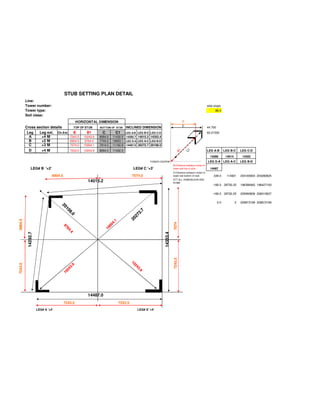
This document provides details of a stub setting plan for a transmission tower, including: - Horizontal and inclined dimensions for the tops and bottoms of each of the four tower legs (A, B, C, D) - Lengths of each leg segment between connection points - Distances from the tower center to the top and bottom of each stub - Notes that all dimensions are in millimeters
Copy of stub setting 1
- 1. STUB SETTING PLAN DETAIL Line: Tower number: side slope Tower type: 89.4 Soil class: HORIZONTAL DIMENSION B C Cross section details TOP OF STUB BOTTOM OF STUB INCLINED DIMENSION 44.700 Leg Leg ext. Ch.Ext. B B1 C C1 LEG A-B LEG B-C LEG C-D 63.21535 A +4 M 7243.5 10243.9 8084.0 11432.5 14292.7 14015.2 14353.4 B +2 M 6904.5 9764.4 7745.0 10953.1 LEG D-A LEG A-C LEG B-D C +3 M 7074.0 10004.1 7914.5 11192.8 14487.0 20272.7 20108.0 D +4 M 7243.5 10243.9 8084.0 11432.5 LEG A-B LEG B-C LEG C-D B1 1 C 14289 14014 14352 TOWER CENTRE LEG D-A LEG A-C LEG B-D BI:Distance between center of LEG# B '+2' LEG# C '+3' tower and top of stub 14487 CI:Distance between center of 6904.5 7074.0 tower and bottom of stub 339.0 114921 204165904 204280825 ATT:ALL DIMENSUION ARE 14015.2 IN MM -169.5 28730.25 196398462 196427193 -169.5 28730.25 205990806 206019537 0.0 0 209873169 209873169 20 10 10 10 7 8. 2. 0 0 0 27 20 6904.5 1 4. 7074 00 97 7 76 10 4... 14292.7 14353.4 4 7243.5 10 7243.5 9 2 24 3. 24 3.. 9 10 14487.0 7243.5 7243.5 LEG# A '+4' LEG# D '+4'