際際滷

際際滷Share a Scribd company logo
1


ProE Tip of the Week: Drag Component
Define your assembly components with the pin constraint in order to drag them around an axis
Drag Component- Step #1: Define the assembly position of the static parts
                                                                              2


                                                                        Pin


                                            Support arms
Drag Component- Step #2: Insert the rotating component using a pin constraint set
                                                                                                                                3


                      2.A Use the pin constraint set                     2.B Define the axis of rotation
                                                                                              Select the axis through the
                                    Pin axis                                                  pivot hole on the rotating part


                                                                                              Select the axis through the
                                                                                              center of the pin


                                                       Pivot hole axis
Drag Component- Step #3: Define the placement of the rotating component by centering it in the assembly
                                                                                                                     4

                                                            Define the translation
                                                                          Mate the rotating side surface
                                                                          to the support arm side surface


                                                                          Offset it from the support arm side
                                                                          surface so its centered in the assembly
Drag Component- Step #4: Define the start position and the rotation limits
                                                                                                                               5

                                                              Define the rotation limits
                                                                              Mate the rotating back surface to the
                                                                              support arm back surface  this defines
                                                                              the start position

                                                                              Use the support arm back surface


                                          Start point
                                       (Current Position)

                                        Minimum value
                                        allowed to drag
                                                                                                             Maximum value
                                      (Back to start point)
                                                                                                             allowed to drag


                                                                  These values can be changed
                                                                     to fit your application
Drag Component- Step #5: Use the drag component icon to rotate the component using the pre-defined values
                                                                                                                         6
                 5.A Click the drag component icon
                 (You may need to add this icon   to your toolbar)


                                                                                         5.C Select any edge / surface
   5.B Select any edge / surface                                                         on the rotating component
   on the rotating component                                                             and drag it to the fully
                                                                                         rotated position (90deg)

More Related Content

PDT Engineering: ProE Tip #014

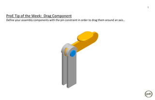
  • 1. 1 ProE Tip of the Week: Drag Component Define your assembly components with the pin constraint in order to drag them around an axis
  • 2. Drag Component- Step #1: Define the assembly position of the static parts 2 Pin Support arms
  • 3. Drag Component- Step #2: Insert the rotating component using a pin constraint set 3 2.A Use the pin constraint set 2.B Define the axis of rotation Select the axis through the Pin axis pivot hole on the rotating part Select the axis through the center of the pin Pivot hole axis
  • 4. Drag Component- Step #3: Define the placement of the rotating component by centering it in the assembly 4 Define the translation Mate the rotating side surface to the support arm side surface Offset it from the support arm side surface so its centered in the assembly
  • 5. Drag Component- Step #4: Define the start position and the rotation limits 5 Define the rotation limits Mate the rotating back surface to the support arm back surface this defines the start position Use the support arm back surface Start point (Current Position) Minimum value allowed to drag Maximum value (Back to start point) allowed to drag These values can be changed to fit your application
  • 6. Drag Component- Step #5: Use the drag component icon to rotate the component using the pre-defined values 6 5.A Click the drag component icon (You may need to add this icon to your toolbar) 5.C Select any edge / surface 5.B Select any edge / surface on the rotating component on the rotating component and drag it to the fully rotated position (90deg)