10. pb air_conditioning_eng
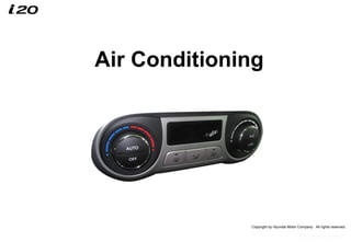
- 1. Copyright by Hyundai Motor Company. All rights reserved. Air Conditioning
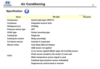
- 2. 2Air Conditioning TB: SEMI CTR TYPE : G/BOX capacity 5~6ℓ G/BOX (5ℓ) SEMI CTR HVAC CTR MT’G HVAC G/BOX (15ℓ) PB: CTR TYPE : G/BOX capacity 15ℓ Specification Items PB (i20) Remarks Compressor Swash plate type (10PA17) Condenser Integrated receiver drier Refrigerant (cc) 570±20g Pressure sensor type APT HVAC type Center mounting type Cooling fan Single fan Cooling fan control Relay (Low/High) Fin thermo sensor Inserted in evaporator Blower motor Auto 8step (Manual 4steps) FATC AQS sensor not applied In-car sensor applied (Motor type), No humidity sensor Photo sensor located in the center of crash pad Water temperature sensor signal is used Feedback type (position sensor embedded) Diagnosis by control panel or scanner
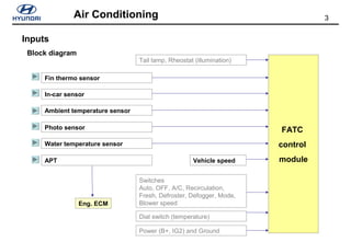
- 3. 3Air Conditioning Inputs Block diagram Tail lamp, Rheostat (illumination) Dial switch (temperature) Power (B+, IG2) and Ground FATC control module Fin thermo sensor In-car sensor Ambient temperature sensor Photo sensor Water temperature sensor Switches Auto, OFF, A/C, Recirculation, Fresh, Defroster, Defogger, Mode, Blower speed APT Eng. ECM Vehicle speed
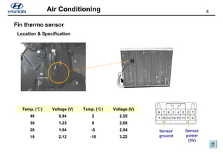
- 4. 4Air Conditioning Fin thermo sensor Location & Specification Temp. ( )℃ Voltage (V) Temp. ( )℃ Voltage (V) 40 0.94 2 2.55 30 1.25 0 2.66 20 1.64 -5 2.94 10 2.12 -10 3.22 Sensor power (5V) Sensor ground
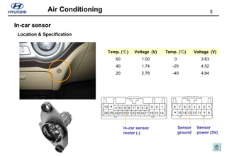
- 5. 5Air Conditioning In-car sensor Location & Specification Temp. ( )℃ Voltage (V) Temp. ( )℃ Voltage (V) 60 1.00 0 3.83 40 1.74 -20 4.52 20 2.78 -40 4.84 Sensor power (5V) In-car sensor motor (-) Sensor ground
- 6. 6Air Conditioning Ambient temperature sensor Location & Specification Sensor power (signal) FATC Ambient temperature sensor Trip computer Sensor power (signal) Sensor ground
- 7. 7Air Conditioning Photo sensor Location & Specification Sensor power (5V) Sensor ground
- 8. 8Air Conditioning Engine temperature sensor Location & Specification FATC ECT temperature sensor ECM, Cluster
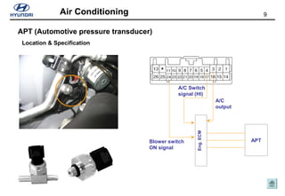
- 9. 9Air Conditioning APT (Automotive pressure transducer) Location & Specification APT A/C Switch signal (HI) Blower switch ON signal Eng.ECM A/C output
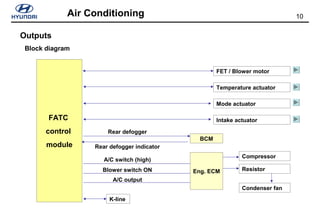
- 10. 10Air Conditioning Outputs Block diagram FATC control module FET / Blower motor Temperature actuator Mode actuator Intake actuator BCM Rear defogger Rear defogger indicator Eng. ECM A/C switch (high) Compressor Resistor Condenser fan K-line Blower switch ON A/C output
- 11. 11Air Conditioning Field Effect Transistor Location & Specification Blower relay FET M F/B D G S FET Gate voltage output FET Drain voltage feedback
- 12. 12Air Conditioning Temperature actuator Location & Specification Temp. actuator Sensor power 5V HI (32°C) 4.55V LO (17°C) 0.45V Temp. actuator Sensor power (5V) Sensor ground Sensor f/back Temp. actuator (Cooling) Temp. actuator (Heating)
- 13. 13Air Conditioning Mode actuator Location & Specification Mode actuator Sensor power 5V Vent 0.45V Bi-level 1.50V Floor 2.65V Mix 3.50V Defroster 4.55V Mode actuator Sensor power (5V) Sensor ground Sensor f/back Mode actuator (Vent) Mode actuator (Defroster)
- 14. 14Air Conditioning Intake actuator Location & Specification Recirculation/Fresh actuator Terminal Voltage B-2 Sensor power(5V) B-11 Sensor feedback B-6 Sensor ground A-22 Fresh mode A-23 Recirculation mode A-connector B-connector
- 15. 15Air Conditioning Owner’s setting procedure Defroster logic control Temperature unit conversion Cannot be changed ! OFF button + AUTO button (3sec)
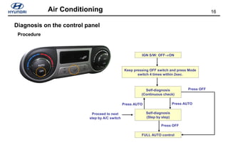
- 16. 16Air Conditioning Diagnosis on the control panel Procedure Proceed to next step by A/C switch IGN S/W: OFF→ON Keep pressing OFF switch and press Mode switch 4 times within 2sec. Self-diagnosis (Continuous check) Self-diagnosis (Step by step) FULL AUTO control Press OFF Press AUTOPress AUTO Press OFF
- 17. 17Air Conditioning PTC (Positive Temperature Coefficient) Heater Location of PTC relay 1, 2 and 3 PTC heater PTC relay 1PTC relay 2PTC relay 3
- 18. 18Air Conditioning PTC (Positive Temperature Coefficient) Heater Engine ECM Heater controller PTC relay 1 Relay ControlBlower motor control Condition satisfied Relay control PTC relay 2 PTC relay 3
