10t causeeffect-2
- 1. Session 10: Cause and Effect Idea Diagrams: Cause and Effect, Affinity and Tree Diagrams 1 Seven Basic Quality Tools 1. Process Mapping / Flow Charts* 2. Check Sheets 3. Pareto Analysis 4. Cause & Effect Diagrams 5. Histograms 6. Scatter Diagrams (XY Graph) 7. Control Charts 2 1 Six Sigma Greenbelt: University of Michigan
- 2. Session 10: Cause and Effect Topics I. Cause and Effect Diagrams A. Ishikawa Fishbone Diagram B. Failure Mode Cause and Effect Diagram II. Affinity Diagram III. Tree Diagram 3 I. Cause-and-Effect Diagrams Cause-and-Effect Diagrams are used to: visually identify potential causes of problems. organize cause-and-effect relationships. assist in root cause analysis. demonstrate knowledge of problem-solving team. Two Common Formats: A. Ishikawa (Fishbone) Diagram B. Failure Mode Cause-and-Effect Diagram 4 2 Six Sigma Greenbelt: University of Michigan
- 3. Session 10: Cause and Effect A. Cause & Effect Diagram (Ishikawa or Fishbone Diagram) Cause Branch Effect â failure twig Branch â Main Categories (Example: 4Mâs - man, method, twiglet machine, material) Effect Twig â 1st Level Causes Twiglets â 2nd Level Causes causes effect 5 Cause-and-Effect Diagrams Classification headings in cause-and-effect diagrams often are derived from qualitative process analysis. 4Mâs (5 or 6 Mâs) Man (personnel), Method, Machine, Material Measurement system (or, include with machine) Mother nature â uncontrollable external issues 6 3 Six Sigma Greenbelt: University of Michigan
- 4. Session 10: Cause and Effect Cause and Effect Analysis Construct the cause and effect diagram as the basis of analysis. Do not stop until you reach root causes (not symptoms). Ask questions and question assumptions. Do not jump to âThe Solution.â 7 Constructing a Cause and Effect Diagram Decide the problem to be analyzed. Draw and label the effect line. Draw and label the cause branches (e.g., 4Mâs). Ask âwhyâ problem occurs to determine first level causes Continue to determine the next level of causes. Try not to stop until you reach root causes (vs. symptoms). Highlight likely root causes. 8 4 Six Sigma Greenbelt: University of Michigan
- 5. Session 10: Cause and Effect Creating a Cause and Effect Diagram Effect Effect - failure 9 Elements of a Cause and Effect Diagram Man Method Effect Branch - broad categories, i.e. 4 Mâs Machine Material 10 5 Six Sigma Greenbelt: University of Michigan
- 6. Session 10: Cause and Effect Elements of a Cause and Effect Diagram Man Method 1st Level Cause Effect Twig - 1st Level Cause Machine Material 11 Elements of a Cause and Effect Diagram Man Method 2nd Level Cause Effect Machine Material 12 6 Six Sigma Greenbelt: University of Michigan
- 7. Session 10: Cause and Effect Lecture Exercise: Create a Cause and Effect Diagram Create a Cause and Effect Diagram for the following problem: Effect: customer dissatisfaction for delayed airline flight departures Use the following Cause Branches: Machine (Equipment); Man (Personnel); Method; Materials; Environment 13 Lecture Exercise: Machine Machine Gate not Mechanical working Flight Delays 14 7 Six Sigma Greenbelt: University of Michigan
- 8. Session 10: Cause and Effect Lecture Exercise: Man Machine Gate Man not Late Mechanical working Crew Late Cleaning Pilot Late Flight Delays 15 Lecture Exercise: Method Machine Gate Man not Late Mechanical working Crew Late Cleaning Pilot Late Flight Delays Gate Boarding blocked Process Unclear Procedure Method 16 8 Six Sigma Greenbelt: University of Michigan
- 9. Session 10: Cause and Effect Lecture Exercise: Materials Machine Gate Man not Late Mechanical working Crew Late Cleaning Pilot Late Flight Delays Late Late Meals Baggage Gate Boarding blocked Process Unclear Late Procedure Materials Method Fuel 17 Lecture Exercise: Environment Machine Gate Man not Late Mechanical working Crew Late Cleaning Environment Pilot Late Weather FAA Delay Flight Delays Late Late Meals Baggage Gate Boarding blocked Process Unclear Late Procedure Materials Method Fuel 18 9 Six Sigma Greenbelt: University of Michigan
- 10. Session 10: Cause and Effect B. Failure Mode Cause-and-Effect Diagram Methods Note: may have multiple effects, Machinery and/or multiple causes Downstream End-user Material Failure Process Operation Mode Man (Person) Environment Causes ||| Effects 19 Failure Mode Cause-and-Effect Diagram (Airline Example) Man Late Crew Method Boarding Process Failure Equipment Mode Customer Missing Lost Dissatisfaction Connections Profits Gate Not Working Material Late Fuel Flight Does Not Leave On-Time Late Baggage Environment Severe Weather Causes ||| Effects 20 10 Six Sigma Greenbelt: University of Michigan
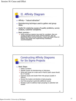
- 11. Session 10: Cause and Effect II. Affinity Diagram Affinity â ânatural attractionâ Brainstorming technique used to gather and group ideas. Useful for analyzing causes of quality problems, survey analysis, customer complaints. Basic premise â while numerous reasons may exist for a problem, they are usually grouped around some common themes. And, by identifying these common themes, a team can better focus on finding root causes and implementing multilateral recommendations. 21 Constructing Affinity Diagrams for Six Sigma Projects Basic Steps: Select a problem. Identify causes via brainstorming or interviews. Write each cause on a note card or Post-It (each cause should be 2-7 words) Examine causes and cluster them into groups (usually in silence). Review the clusters and decide on best grouping. Use final grouping to generate additional causes. Develop a plan to address major groupings or potential root causes. 22 11 Six Sigma Greenbelt: University of Michigan
- 12. Session 10: Cause and Effect Example: Software Re-Design Project Six Sigma Project Problem: employees are complaining about the limitations of an internally developed excel-based program used in the Production Part Approval Process. Software Product â provides a statistical summary of the part characteristics to verify production readiness. Six Sigma Team was formed to identify causes of the complaints. Team interviewed various users for input. Can you think of any likely concerns based on past experience? 23 Exercise: Affinity Diagram (create 2-4 groupings of concerns) 1. Difficult to navigate 2. No standardized summary reports 3. Limited graphical summary reports 4. Cannot analyze multiple characteristics 5. Difficult to change part specifications 6. Cannot handle blank cells within data range 7. Few user friendly features 8. Difficult to import/export data 9. No formula protection 10. No outlier analysis 11. Takes too long to setup print feature 12. Data Files too big (programming in every file) 13. Too much manual input 14. No customized features to perform analysis 15. No customized naming of files 24 12 Six Sigma Greenbelt: University of Michigan
- 13. Session 10: Cause and Effect Groupings Suppose the team has identified 3 Groupings for the concerns. Place the previous concerns into the following: A. Data Analysis Capability B. Functionality â Ease of Use C. Programming Efficiency 25 Affinity Diagram â Production Part Approval Software A. Data Analysis Capability B. Functionality â Ease of Use Limited graphical summary reports Difficult to navigate Cannot analyze multiple characteristics Few user friendly features Difficult to change part specifications Takes too long to setup print feature No standardized summary reports Too much manual input No outlier analysis No customized naming of files No customized features to perform analysis C. Programming Efficiency Cannot handle blank cells within data range Difficult to import/export data No formula protection Data Files too big (programming in every file) 26 13 Six Sigma Greenbelt: University of Michigan
- 14. Session 10: Cause and Effect Affinity Diagram â Next Steps After grouping all of the data, you should brainstorm for additional causes / concerns. (Grouping â generate more ideas) Case Study â For this case study, a list of recommendations were developed to improve the software tool including converting the tool into a read- only application. 27 III. Tree Diagram A tree diagram provides a hierarchy of cause-effect relationships. Often need to keep asking why to better understand root cause(s) of problems. Cause âĶ Cause Cause Problem Cause âĶ Cause Cause âĶ. WHY? 28 14 Six Sigma Greenbelt: University of Michigan
- 15. Session 10: Cause and Effect Tree Diagram Example: Loan Case Study Why? Loan takes too long Internal processing errors Loan application errors from customer Loan officers do not know all the details to obtain for a lending program Branch Managers do not provide standard guidelines of lender programs Central office does not provide branch managers with support to develop standards. Loan Application Internal Errors Processing Errors Loan take Lender Program changes Too long Loan Application Errors To process Underwriting Delays waiting for external Delays Underwriter to process loan âĶ. 29 Tree Diagram â Alternative Use Tree Diagrams also may be used in the IMPROVE PHASE to identify ways or means to complete a task or objective. Means âĶ Means Means Objective Means âĶ Means Means âĶ. How? 30 15 Six Sigma Greenbelt: University of Michigan


