18 FM_Demodulators-Foster_Seeley_and_Ratio_Detector.pdf
- 1. 1 Foster-Seeley Discriminator Prof. Dr. G.Aarthi, Associate Professor, SENSE
- 2. Foster-Seeley (Phase) Discriminator • In this all the tuned circuits are tuned to the same frequency. • Balanced Slope Detector circuit with some changes is used. • This circuit yields far better linearity than slope detection. 2
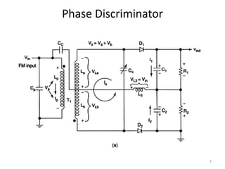
- 4. The capacitances Cc,C1 and C2 are chosen such that they are short circuits for the IF center frequency. The IF signal is fed directly across L3. VL3ï‚» VIN Incoming IF is inverted 180 degree by T1 and divided equally between La and Lb. So Voltage across diode= VIN + Secondary Voltage/2 Phase Discriminator 4
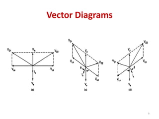
- 5. When IF center frequency (fc)=fo, then secondary current Is is in phase with Secondary voltage Vs and 180o out of phase with VL3. VLa and VLb are 180o out of phase with each other and 90o out of phase with VL3. At Resonant Frequency 5
- 6. VD1=VL3+VLa and VD2=VL3+VLb The voltages across the diodes D1 and D2 are equal. Therefore, I1 and I2 are equal. C1 and C2 charge to equal Magnitude voltages except With opposite polarities Vout=Vc1-Vc2=0V At Resonant Frequency 6
- 7. If IF(fc)>fo then XL>XC, the secondary tank circuit impedance becomes inductive. Is lags Vs by some angle θ which is proportional to the magnitude of the frequency deviation. The vector sum of voltage across D1>D2 C1 charges and C2 discharges and Vout=Vc1-Vc2=+ve Voltage IF goes above Resonance 7
- 8. If IF(fc)<fo then XL<XC, the secondary tank circuit impedance becomes capacitive. Is leads Vs by some angle θ which is proportional to the magnitude of the frequency deviation. The vector sum of voltage across D1<D2 C1 discharges and C2 charges and Vout=Vc1-Vc2= -ve Voltage IF goes below Resonance 8
- 10. Voltage Vs Frequency Response 10
- 11. Phase Discriminator • It is much easier to align, as there are now two tuned circuits and both are tuned to the same frequency. • Linearity is quite better, as circuit relies less on frequency & more on primary-secondary phase relation, which is quite linear. • Only drawback is, there is no provision for amplitude limiting. 11
- 12. Ratio- Detector • Ratio detector demodulator is modified Foster- Seeley circuit in order to incorporate amplitude limiting. • In Foster-Seeley discriminator the sum of voltages VD1+VD2 should remain constant. • Their difference should vary due to variation in input frequency. 12
- 13. Ratio-detector • But practically speaking any variation in the amplitude of input signal, also has impact on sum of VD1+VD2, leading to distortion. • Ratio-detector circuit eliminates this variation of VD1+VD2, and performs the function of amplitude limiter also. 13
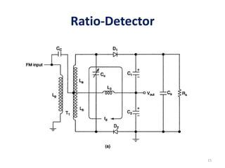
- 14. Ratio-Detector Changes made in Foster-Seeley discriminator: • One of The diodes has been reversed. • A large capacitor has been placed between points, from where output was taken. 14
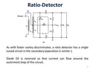
- 16. Ratio-Detector As with foster seeley discriminator, a ratio detector has a single tuned circuit in the secondary.(operation is similar ). Diode D2 is reversed so that current can flow around the outermost loop of the circuit. 16
- 17. Ratio-Detector After several input cycles , shunt capacitor Cs charges to approximately the peak voltage across the secondary winding of T1. The time constant for Rs and Cs is sufficiently long so that rapid changes in the amplitude of the input signal, have no effect on the average voltage across Cs. 17
- 18. Ratio-Detector C1 and C2 charge and discharge proportional to frequency changes in the input signal and are relatively immune to amplitude variations. At Resonance, the output voltage is divided equally between C1 and C2 and redistributed as the input frequency is deviated above and below resonance. 18
- 19. Ratio-Detector At resonance ,Vout is not equal to 0V, but rather to one half of the voltage across the secondary windings of T1. 19
- 20. Voltage Vs Frequency Response 20
- 21. Ratio-Detector Advantages • Amplitude limiting is possible. • Linearity is quite good as compared to others. So quite often used in high quality receivers. 21
- 22. Ratio-Detector Dis-advantages • Under critical noise conditions, such as satellite receivers, where demodulator noise performance becomes very significant, even this demodulator is found wanting. • Under these conditions more advanced demodulators such as Phase Locked Loop are used. 22
