1.general block diagram
âĒDownload as PPTX, PDFâĒ
0 likesâĒ232 views

This course covers electric drive systems controlled by power electronic converters. It discusses DC drives, induction motor drives controlled from the stator side and rotor side, and synchronous motor drives. Students will learn about drive characteristics and modeling, DC drive configurations, closed-loop control of induction motors, efficient speed control methods for induction motors, and control techniques for synchronous motors. The course aims to provide an understanding of electric drive performance and applications in various industries.


1.general block diagram
- 1. EE T72 - SOLID STATE DRIVES
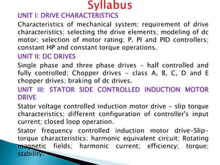
- 2. UNIT I: DRIVE CHARACTERISTICS Characteristics of mechanical system; requirement of drive characteristics; selecting the drive elements; modeling of dc motor; selection of motor rating; P. PI and PID controllers; constant HP and constant torque operations. UNIT II: DC DRIVES Single phase and three phase drives - half controlled and fully controlled; Chopper drives - class A, B, C, D and E chopper drives; braking of dc drives. UNIT III: STATOR SIDE CONTROLLED INDUCTION MOTOR DRIVE Stator voltage controlled induction motor drive - slip torque characteristics; different configuration of controller's input current; closed loop operation. Stator frequency controlled induction motor drive-Slip- torque characteristics; harmonic equivalent circuit; Rotating magnetic fields; harmonic current; efficiency; torque; stability.
- 3. UNIT IV: ROTOR SIDE CONTROLLED INDUCTION MOTOR DRIVE Rotor Resistance Control: slip-torque characteristics; equivalent chopper resistance; chopper circuit filter; constant current operation. Slip Power Recovery Scheme: Slip power recovery scheme; sub synchronous operation; performance prediction; input power factor. UNIT V: SYNCHRONOUS MOTOR DRIVES Open loop volts/hertz control and self-control of synchronous motor: Marginal angle control and power factor control. Introduction to vector control - Principles and types.
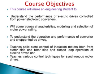
- 4. ï― This course will make an engineering student to ï― Understand the performance of electric drives controlled from power electronic converters. ï― Will come across characteristics, modeling and selection of motor power rating. ï― To understand the operation and performance of converter and chopper fed dc drives. ï― Teaches solid state control of induction motors both from stator side and rotor side and closed loop operation of electric drives and ï― Teaches various control techniques for synchronous motor drives.
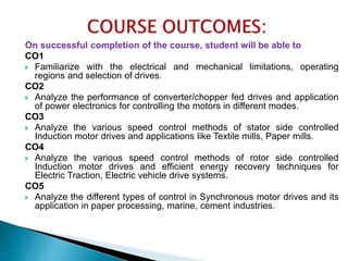
- 5. On successful completion of the course, student will be able to CO1 ï― Familiarize with the electrical and mechanical limitations, operating regions and selection of drives. CO2 ï― Analyze the performance of converter/chopper fed drives and application of power electronics for controlling the motors in different modes. CO3 ï― Analyze the various speed control methods of stator side controlled Induction motor drives and applications like Textile mills, Paper mills. CO4 ï― Analyze the various speed control methods of rotor side controlled Induction motor drives and efficient energy recovery techniques for Electric Traction, Electric vehicle drive systems. CO5 ï― Analyze the different types of control in Synchronous motor drives and its application in paper processing, marine, cement industries.
- 11. Electrical Energy (Rotational Force) Mechanical Energy Motor
- 12. 12
- 13. Electrical Drive ïSystems employed for motion control are called as Drives. ïIt may employ any of prime movers such as diesel or petrol engines, gas or steam turbines, steam engines, hydraulic motors and electric motors, for supplying mechanical energy for motion control. ïDrives employing electric motors are called as Electrical Drives.
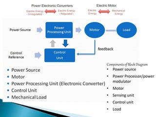
- 15. Block diagram for Electrical Drives
- 16. Components of Block Diagram âĒ Power source âĒ Power Processor/power modulator âĒ Motor âĒ Sensing unit âĒ Control unit âĒ Load
- 17. âĒ Single phase AC âĒ Three Phase AC âĒ DC supply
- 18. Electrical Source Voltage Rating::110V, 230V, 415V, 25KV Current Rating:: 0.5A, 1A, 2A, 3A, 5A, 10A, 15A, 20A, 30A Frequency-50Hz Voltage Rating::5V, 6V, 12V, 24V, 48V, 220V Current Rating:: 0.2A, 0.3A, 0.5A, 1.5A, 1A, 2A, 2.5A, 2A, 3A There is no Frequency âĒ Current âĒ Voltage
- 19. âĒ Modulates flow of power from the source to the motor in such a manner that motor is imparted speed torque characteristics required by the load âĒ During transient operations , such as starting, braking and speed reversal . It restricts the source and motor current within permissible value âĒ Converts electrical energy of the source in the form suitable to motor. âĒ Selects the mode of operation
- 20. classification of power modulator: (a) Converters: Need for converter arises when nature of the available electrical power is different than what is required for the motor. 1.ac to dc converter 2.dc to dc converter 3.Inverters 4.cycloconverters
- 21. ï Variable resistors are commonly used for the control of dc and ac drives. ï Can be controlled manually or automatic. ï Stepless variation of resistance can be obtained using a semiconductor switch in parallel with a fixed resistance; ï variation of duty ratio of the switch gives a stepless variation in effective value of the resistance. (b)Variableimpedances
- 22. (c)SwitchingCircuits: ï― For changing motor connections to change itâs quadrant of operation ï― For operating motors and drives according to predetermined sequence ï― To disconnect motor when abnormal conditions occur
- 23. Power Converters
- 24. Power Converters
- 25. Converters Converter is used to convert the AC Voltage into DC Voltage Converter AC Voltage DC Voltage T V T V
- 26. Inverters Inverter is used to convert the DC Voltage into AC Voltage Inverter DC Voltage AC Voltage T V T V
- 27. Chopper Chopper is used to convert the fixed DC Voltage into Variable DC Voltage Chopper Fixed DC Voltage Variable DC Voltage T V T V
- 28. Cyclo Converters Cyclo Converter is used to convert the Fixed Frequency into Variable Frequency Converter Fixed Frequency Variable Frequency
- 29. ELECTRICAL MOTORS The possible form of drive motors are (a). Dc motor fed from DC supply (chopper) (b) Dc motor fed from AC supply (rectifier) (c) Ac motor fed from AC supply (AC regulator)
- 30. AC Motor Induction Motor Compound Motor Synchronous Motor Series Motor Shunt Motor DC Motor Special Type Motor Stepper Motor BLDC Motor Reluctance Motor Types of Motor Universal Motor
- 31. Most commonly used electrical drives are DC MOTORS 1. Shunt motor 2. Series motor 3. Compound motor 4. Permanent magnet motor AC MOTORS INDUCTION MOTORS 1. Squirrel cage IM 2. Wound rotor IM 3. Linear IM SYNCHRONOUS MOTORS 1. Wound field motor 2. Permanent magnet motor Brushless dc motors Stepper motors Switched reluctance motors
- 32. Sensing Unit ï Sensor is used to sense the physical quantity and convert it to electrical quantity ï It senses the certain drive parameter like motor current and speed. ï It mainly required either for protection or for closed loop operation. Sensor Physical Quantity Electrical Quantity
- 33. Sensing Unit In this unit, there are two functions are performed i. Speed Sensing ii. Current Sensing ïŽ SPEED SENSING Speed sensing is required for implementation of closed loop speed control schemes. Speed is usually sensed by Tachometers. When very high speed accuracies required, as in computer peripherals and paper mills, etc., digital tachometers are used ïŽ CURRENT SENSING Current sensing employs two methods 1. Use of current sensor employing hall effect
- 34. Control Unit âĒ It controls the system motion without any damages according to the sensing unit along with input command. âĒ The control unit controls the power modulator which operates at small voltage and power levels. The control unit also operates the power modulator as desired. âĒ Control unit consist of ï digital integrated circuit, ï Transistor and ï Microprocessor
- 35. Load âĒ Normally loads are designed for accomplishing the given task. âĒ For example ï Fan, ï Pumps, ï Robots, ï Washing Machine
- 36. âĒ The load has certain torque speed characteristic âĒ A motor having speed torque characteristic and capabilities compatible to the load requirement is chosen
- 37. âĒ Have flexible control characteristics âĒ Available in wide range of torque , speed and power âĒ Not pollute the environment âĒ Adaptable in almost any operating conditions âĒ Can operate in all the four quadrant of operations âĒ Smooth speed control