20ME702ŌĆō MECHATRONICS -UNIT-4.ppt
ŌĆóDownload as PPT, PDFŌĆó
28 likesŌĆó245 views

This document provides an overview of programmable logic controllers (PLCs). It describes the basic structure of a PLC including input/output modules, a central processing unit, memory, and a programming unit. The document outlines how PLCs are used for automation in industrial processes by replacing hardwired relay controls. It also discusses PLC programming using ladder logic and provides examples of logic functions, timers, counters, and data handling capabilities of PLCs. Selection factors for choosing a suitable PLC for an application are also mentioned.
20ME702ŌĆō MECHATRONICS -UNIT-4.ppt
- 1. UNIT 4 PROGRAMMABLE LOGIC CONTROLLER
- 2. UNIT IV PROGRAMMABLE LOGIC CONTROLLER ŌĆó Introduction ŌĆō Basic structure ŌĆō Input and output processing ŌĆō Programming ŌĆō Mnemonics ŌĆō Timers, counters and internal relays ŌĆō Data handling ŌĆō Selection of PLC.
- 3. Content ŌĆó Introduction ŌĆó Basic structure ŌĆó Input and output processing ŌĆó Programming ŌĆó Mnemonics ŌĆó Timers, counters and internal relays ŌĆó Data handling ŌĆó Selection of PLC
- 4. PROGRAMMABLE LOGIC CONTROLLER ŌĆó A Programmable Logic Controller(PLC) is a digital computer used for automation of typically industrial electromechanical processes, such as control of machinery on factory assembly lines, amusement rides or light fixtures.
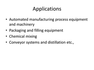
- 5. Applications ŌĆó Automated manufacturing process equipment and machinery ŌĆó Packaging and filling equipment ŌĆó Chemical mixing ŌĆó Conveyor systems and distillation etc.,
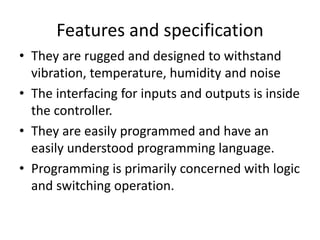
- 6. Features and specification ŌĆó They are rugged and designed to withstand vibration, temperature, humidity and noise ŌĆó The interfacing for inputs and outputs is inside the controller. ŌĆó They are easily programmed and have an easily understood programming language. ŌĆó Programming is primarily concerned with logic and switching operation.
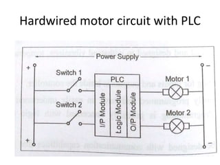
- 8. Hardwired motor circuit with PLC
- 10. ŌĆó PLC is designed as a replacement for the hardwired relay and timer logic, where PLC provides ease and flexibility of control based on programming and executive logical instruction. ŌĆó The internal functions such as timers, counter and shift registers making sophisticated control possible using even the smallest PLC.
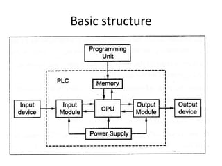
- 11. ŌĆó PLC capable of performing function such as ŌĆō counting, ŌĆō logistics, ŌĆō numerical application, ŌĆō comparing and processing of signals. ŌĆó A PLC is divided in to 4 parts. They are ŌĆō Input/output module (I/O) ŌĆō Central processing Unit (CPU) ŌĆō Memory ŌĆō Programming unit
- 12. i) Input/output module (I/O) ŌĆó It is used to transfer the data between external devices and CPU ŌĆó It is incorporated into PLC in two ways I. Fixed I/O ŌĆō it is a small unit that comes in one piece with processor i.e., the I/O terminals cannot be changed in fixed I/O II. Modular I/O ŌĆō it is packed together i.e., there are several compartment of I/O module are plugged together.
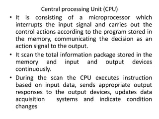
- 13. Central processing Unit (CPU) ŌĆó It is consisting of a microprocessor which interrupts the input signal and carries out the control actions according to the program stored in the memory, communicating the decision as an action signal to the output. ŌĆó It scan the total information package stored in the memory and input and output devices continuously. ŌĆó During the scan the CPU executes instruction based on input data, sends appropriate output responses to the output devices, updates data acquisition systems and indicate condition changes
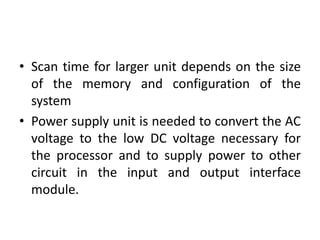
- 14. ŌĆó Scan time for larger unit depends on the size of the memory and configuration of the system ŌĆó Power supply unit is needed to convert the AC voltage to the low DC voltage necessary for the processor and to supply power to other circuit in the input and output interface module.
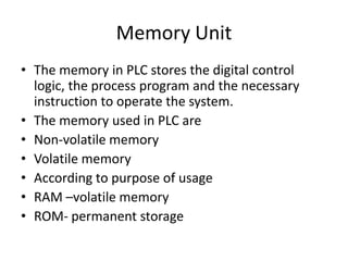
- 15. Memory Unit ŌĆó The memory in PLC stores the digital control logic, the process program and the necessary instruction to operate the system. ŌĆó The memory used in PLC are ŌĆó Non-volatile memory ŌĆó Volatile memory ŌĆó According to purpose of usage ŌĆó RAM ŌĆōvolatile memory ŌĆó ROM- permanent storage
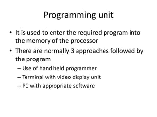
- 16. Programming unit ŌĆó It is used to enter the required program into the memory of the processor ŌĆó There are normally 3 approaches followed by the program ŌĆō Use of hand held programmer ŌĆō Terminal with video display unit ŌĆō PC with appropriate software
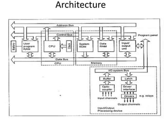
- 17. Architecture
- 18. ŌĆó Buses ŌĆō Data buses ŌĆō it is used for communicating data b/n elements ŌĆō Address buses-it is used to read the address of locations for accessing stored data ŌĆō Control buses- it is used for internal control action carried by the CPU ŌĆō System buses- it is used for communication b/n Input/output ports and input/output units
- 19. ŌĆó Memory ŌĆō RAM ŌĆō ROM ŌĆó PROM ŌĆó EPROM ŌĆó Electrically EPROM
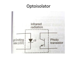
- 20. Optoisolator ŌĆó Electrical connection from the external world is usually by means of optoisolator ŌĆó When a digital pulses passes through the LED, a pulse of Infrared radiation is produced. ŌĆó This pulses is detected by the phototransistor and gives rise to a voltage in that circuit.
- 21. Optoisolator
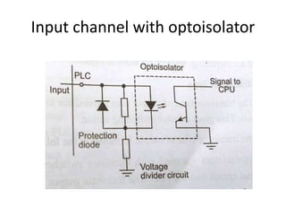
- 22. Input channel with optoisolator
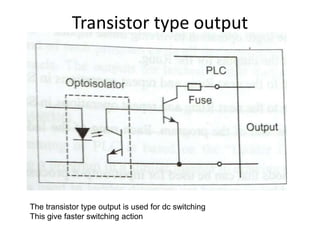
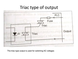
- 23. ŌĆó Common input voltage is 5V and 24V ŌĆó Output voltage is 24V and 240V ŌĆó Output are often specified as being of ŌĆō Relay type ŌĆō Transistor type ŌĆō Triac type
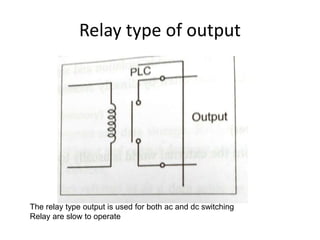
- 24. Relay type of output The relay type output is used for both ac and dc switching Relay are slow to operate
- 25. Transistor type output The transistor type output is used for dc switching This give faster switching action
- 26. Triac type of output The triac type output is used for switching AC voltages
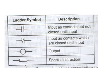
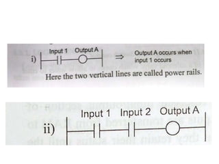
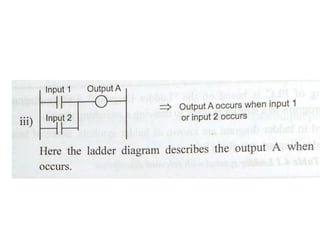
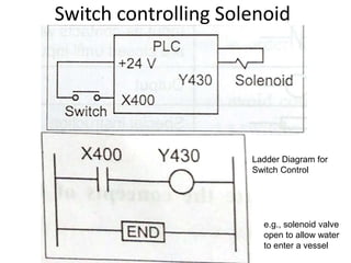
- 27. Programming ŌĆó The programming of PLC is based on the ladder diagram. ŌĆó Ladder diagram involve writing a program in a similar maner to drawing a switching circuit.
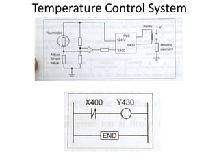
- 31. Switch controlling Solenoid e.g., solenoid valve open to allow water to enter a vessel Ladder Diagram for Switch Control
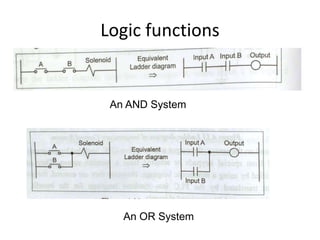
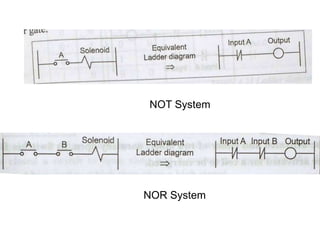
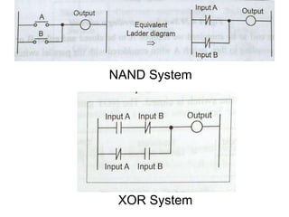
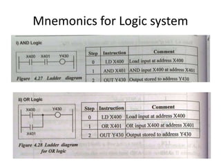
- 33. Logic functions An AND System An OR System
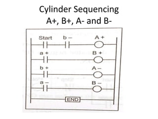
- 36. Cylinder Sequencing A+, B+, A- and B-
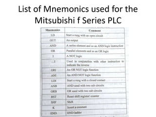
- 37. List of Mnemonics used for the Mitsubishi f Series PLC
- 38. Mnemonics for Logic system
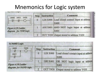
- 39. Mnemonics for Logic system
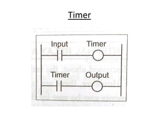
- 40. Timer
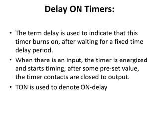
- 41. Delay ON Timers: ŌĆó The term delay is used to indicate that this timer burns on, after waiting for a fixed time delay period. ŌĆó When there is an input, the timer is energized and starts timing, after some pre-set value, the timer contacts are closed to output. ŌĆó TON is used to denote ON-delay
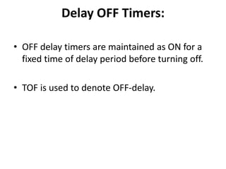
- 42. Delay OFF Timers: ŌĆó OFF delay timers are maintained as ON for a fixed time of delay period before turning off. ŌĆó TOF is used to denote OFF-delay.
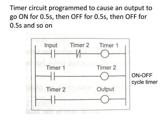
- 43. Timer circuit programmed to cause an output to go ON for 0.5s, then OFF for 0.5s, then OFF for 0.5s and so on ON-OFF cycle timer
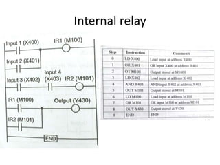
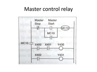
- 44. Internal relay
- 45. COUNTERS ŌĆó Counters are used to count a specified number of contact operatio Types of Counters: ŌĆó Up Counters ŌĆó Down Counters ns
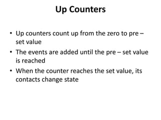
- 46. Up Counters ŌĆó Up counters count up from the zero to pre ŌĆō set value ŌĆó The events are added until the pre ŌĆō set value is reached ŌĆó When the counter reaches the set value, its contacts change state
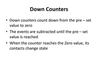
- 47. Down Counters ŌĆó Down counters count down from the pre ŌĆō set value to zero ŌĆó The events are subtracted until the pre ŌĆō set value is reached ŌĆó When the counter reaches the Zero value, its contacts change state
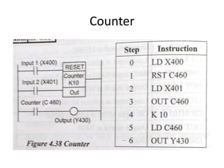
- 48. Counter
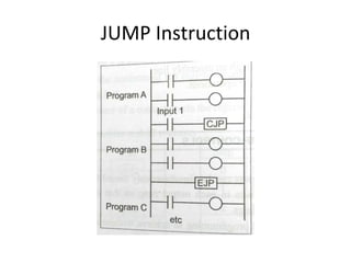
- 50. JUMP Instruction
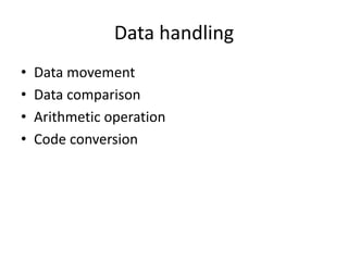
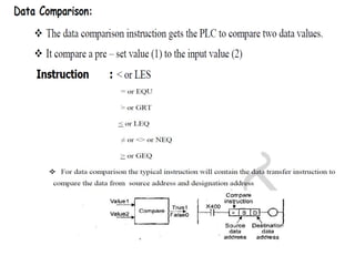
- 51. Data handling ŌĆó Data movement ŌĆó Data comparison ŌĆó Arithmetic operation ŌĆó Code conversion
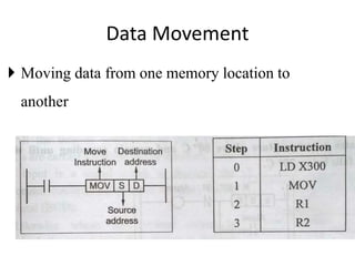
- 52. Data Movement ’üĮ Moving data from one memory location to another
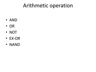
- 54. Arithmetic operation ŌĆó AND ŌĆó OR ŌĆó NOT ŌĆó EX-OR ŌĆó NAND
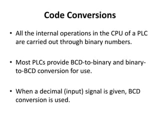
- 55. Code Conversions ŌĆó All the internal operations in the CPU of a PLC are carried out through binary numbers. ŌĆó Most PLCs provide BCD-to-binary and binary- to-BCD conversion for use. ŌĆó When a decimal (input) signal is given, BCD conversion is used.
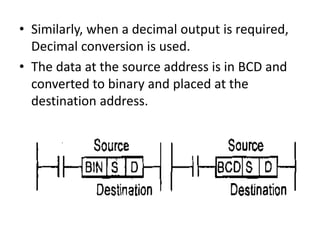
- 56. ŌĆó Similarly, when a decimal output is required, Decimal conversion is used. ŌĆó The data at the source address is in BCD and converted to binary and placed at the destination address.
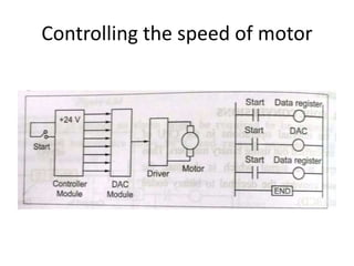
- 57. Controlling the speed of motor
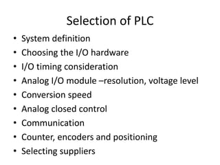
- 58. Selection of PLC ŌĆó System definition ŌĆó Choosing the I/O hardware ŌĆó I/O timing consideration ŌĆó Analog I/O module ŌĆōresolution, voltage level ŌĆó Conversion speed ŌĆó Analog closed control ŌĆó Communication ŌĆó Counter, encoders and positioning ŌĆó Selecting suppliers