![Mobile Communication Technology
according to IEEE (examples)
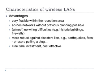
Local wireless networks
WLAN 802.11
802.11a
802.11b
802.11i/e/ŌĆ”/n/ŌĆ”/z/az
802.11g
WiFi
802.11h
Personal wireless nw
WPAN 802.15
802.15.4
802.15.1
802.15.2
Bluetooth
802.15.4a/b/c/d/e/f/gŌĆ”q/r/s
ZigBee
802.15.3
Wireless distribution networks
WMAN 802.16 (Broadband Wireless Access)
[hist.: 802.20 (Mobile Broadband Wireless Access)]
802.16e (addition to .16 for mobile devices)
+ Mobility
WiMAX
802.15.3b/cŌĆ”e
802.15.5, .6 (WBAN), ŌĆ”](https://image.slidesharecdn.com/3-240225064604-ad26b018/85/3-Introduction-Wireless-Local-Area-Networks-ppt-2-320.jpg)


More Related Content
Similar to 3. Introduction Wireless Local Area Networks.ppt (20)
Recently uploaded (20)


![MODULE 01 - CLOUD COMPUTING [BIS 613D] .pptx](https://cdn.slidesharecdn.com/ss_thumbnails/module01-cloudcomputing-250409082345-d719f5bc-thumbnail.jpg?width=560&fit=bounds)


3. Introduction Wireless Local Area Networks.ppt
- 1. Wireless LAN
- 2. Mobile Communication Technology according to IEEE (examples) Local wireless networks WLAN 802.11 802.11a 802.11b 802.11i/e/ŌĆ”/n/ŌĆ”/z/az 802.11g WiFi 802.11h Personal wireless nw WPAN 802.15 802.15.4 802.15.1 802.15.2 Bluetooth 802.15.4a/b/c/d/e/f/gŌĆ”q/r/s ZigBee 802.15.3 Wireless distribution networks WMAN 802.16 (Broadband Wireless Access) [hist.: 802.20 (Mobile Broadband Wireless Access)] 802.16e (addition to .16 for mobile devices) + Mobility WiMAX 802.15.3b/cŌĆ”e 802.15.5, .6 (WBAN), ŌĆ”
- 3. Characteristics of wireless LANs ’üĮ Advantages ’üĮ very flexible within the reception area ’üĮ ad-hoc networks without previous planning possible ’üĮ (almost) no wiring difficulties (e.g. historic buildings, firewalls) ’üĮ more robust against disasters like, e.g., earthquakes, fires - or users pulling a plug... ’üĮ One time investment, cost effective
- 4. Characteristics of wireless LANs ’üĮ Disadvantages ’üĮ typically low bandwidth compared to wired networks (1-10 Mbit/s) due to shared medium, lots of interference ’üĮ different/proprietary solutions, especially for higher bit- rates or low-power, standards take their time (e.g. IEEE 802.11n, ac), devices have to fall back to older/standard solutions ’üĮ products have to follow many national restrictions if working wireless, it takes a very long time to establish global solutions like, e.g., IMT-2000
- 5. Design goals for wireless LANs ŌĆó global, seamless operation ŌĆó low power for battery use ŌĆó no special permissions or licenses needed to use the LAN ŌĆó robust transmission technology ŌĆó simplified spontaneous cooperation at meetings ŌĆó easy to use for everyone, simple management ŌĆó protection of investment in wired networks ŌĆó security (no one should be able to read my data), privacy (no one should be able to collect user profiles), safety (low radiation) ŌĆó transparency concerning applications and higher layer protocols, but also location awareness if necessary ŌĆó ŌĆ”
- 6. Basic Transmission Technologies ’üĮ Infra Red ’üĮ Radio Waves
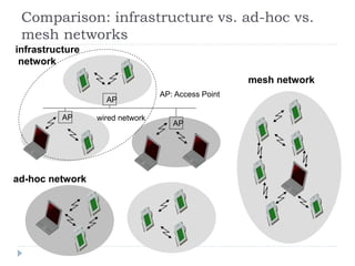
- 7. Comparison: infrastructure vs. ad-hoc vs. mesh networks infrastructure network ad-hoc network AP AP AP wired network AP: Access Point mesh network
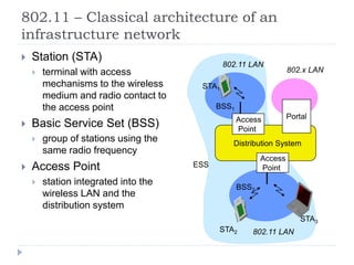
- 8. 802.11 ŌĆō Classical architecture of an infrastructure network ’üĮ Station (STA) ’üĮ terminal with access mechanisms to the wireless medium and radio contact to the access point ’üĮ Basic Service Set (BSS) ’üĮ group of stations using the same radio frequency ’üĮ Access Point ’üĮ station integrated into the wireless LAN and the distribution system Distribution System Portal 802.x LAN Access Point 802.11 LAN BSS2 802.11 LAN BSS1 Access Point STA1 STA2 STA3 ESS
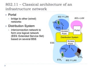
- 9. 802.11 ŌĆō Classical architecture of an infrastructure network ’üĮ Portal ’üĮ bridge to other (wired) networks ’üĮ Distribution System ’üĮ interconnection network to form one logical network (EES: Extended Service Set) based on several BSS Distribution System Portal 802.x LAN Access Point 802.11 LAN BSS2 802.11 LAN BSS1 Access Point STA1 STA2 STA3 ESS
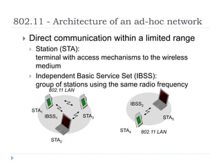
- 10. 802.11 - Architecture of an ad-hoc network ’üĮ Direct communication within a limited range ’üĮ Station (STA): terminal with access mechanisms to the wireless medium ’üĮ Independent Basic Service Set (IBSS): group of stations using the same radio frequency 802.11 LAN IBSS2 802.11 LAN IBSS1 STA1 STA4 STA5 STA2 STA3
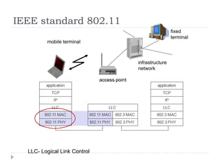
- 11. IEEE standard 802.11 mobile terminal access point fixed terminal infrastructure network LLC- Logical Link Control
- 12. 802.11 - Layers and functions ’üĮ MAC ’üĮ access mechanisms, fragmentation, encryption ’üĮ MAC Management ’üĮ synchronization, roaming, MIB, power management ’üĮ PLCP (Physical Layer Convergence Protocol) ’üĮ clear channel assessment signal (carrier sense) ’üĮ PMD (Physical Medium Dependent) ’üĮ modulation, coding ’üĮ PHY Management ’üĮ channel selection, MIB ’üĮ Station Management ’üĮ coordination of all management functions PMD PLCP MAC LLC MAC Management PHY Management PHY DLC Station Management DLC: Data Link Control MIB: Management Information Base
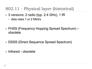
- 13. 802.11 - Physical layer (historical) ’üĮ 3 versions: 2 radio (typ. 2.4 GHz), 1 IR ’üĮ data rates 1 or 2 Mbit/s ’üĮ FHSS (Frequency Hopping Spread Spectrum) ŌĆō obsolete ’üĮ DSSS (Direct Sequence Spread Spectrum) ’üĮ Infrared - obsolete
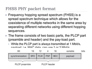
- 14. FHSS PHY packet format ’üĮ Frequency hopping spread spectrum (FHSS) is a spread spectrum technique which allows for the coexistence of multiple networks in the same area by separating different networks using different hopping sequences. ’üĮ The frame consists of two basic parts, the PLCP part (preamble and header) and the pay-load part. ’üĮ While the PLCP part is always transmitted at 1 Mbit/s, payload, i.e. MAC data, can use 1 or 2 Mbit/s.
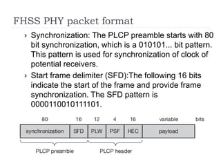
- 15. FHSS PHY packet format ’üĮ Synchronization: The PLCP preamble starts with 80 bit synchronization, which is a 010101... bit pattern. This pattern is used for synchronization of clock of potential receivers. ’üĮ Start frame delimiter (SFD):The following 16 bits indicate the start of the frame and provide frame synchronization. The SFD pattern is 0000110010111101.
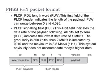
- 16. FHSS PHY packet format ’üĮ PLCP_PDU length word (PLW):This first field of the PLCP header indicates the length of the payload. PLW can range between 0 and 4,095. ’üĮ PLCP signalling field (PSF):This 4 bit field indicates the data rate of the payload following. All bits set to zero (0000) indicates the lowest data rate of 1 Mbit/s. The granularity is 500 kbit/s, thus 2 Mbit/s is indicated by 0010 and the maximum is 8.5 Mbit/s (1111). This system obviously does not accommodate todayŌĆÖs higher data rates.
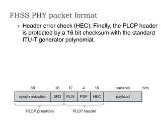
- 17. FHSS PHY packet format ’üĮ Header error check (HEC): Finally, the PLCP header is protected by a 16 bit checksum with the standard ITU-T generator polynomial.
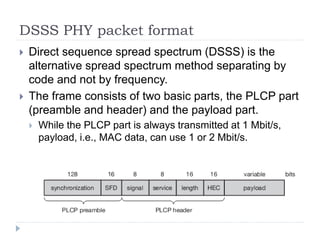
- 18. DSSS PHY packet format ’üĮ Direct sequence spread spectrum (DSSS) is the alternative spread spectrum method separating by code and not by frequency. ’üĮ The frame consists of two basic parts, the PLCP part (preamble and header) and the payload part. ’üĮ While the PLCP part is always transmitted at 1 Mbit/s, payload, i.e., MAC data, can use 1 or 2 Mbit/s.
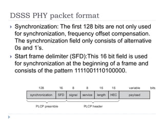
- 19. DSSS PHY packet format ’üĮ Synchronization: The first 128 bits are not only used for synchronization, frequency offset compensation. The synchronization field only consists of alternative 0s and 1ŌĆÖs. ’üĮ Start frame delimiter (SFD):This 16 bit field is used for synchronization at the beginning of a frame and consists of the pattern 1111001110100000.
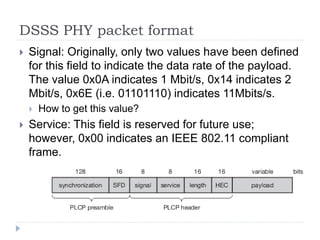
- 20. DSSS PHY packet format ’üĮ Signal: Originally, only two values have been defined for this field to indicate the data rate of the payload. The value 0x0A indicates 1 Mbit/s, 0x14 indicates 2 Mbit/s, 0x6E (i.e. 01101110) indicates 11Mbits/s. ’üĮ How to get this value? ’üĮ Service: This field is reserved for future use; however, 0x00 indicates an IEEE 802.11 compliant frame.
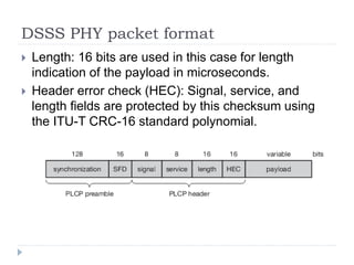
- 21. DSSS PHY packet format ’üĮ Length: 16 bits are used in this case for length indication of the payload in microseconds. ’üĮ Header error check (HEC): Signal, service, and length fields are protected by this checksum using the ITU-T CRC-16 standard polynomial.
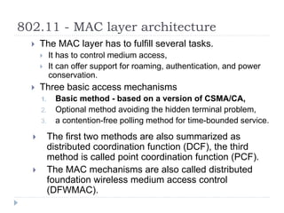
- 22. 802.11 - MAC layer architecture ’üĮ The MAC layer has to fulfill several tasks. ’üĮ It has to control medium access, ’üĮ It can offer support for roaming, authentication, and power conservation. ’üĮ Three basic access mechanisms 1. Basic method - based on a version of CSMA/CA, 2. Optional method avoiding the hidden terminal problem, 3. a contention-free polling method for time-bounded service. ’üĮ The first two methods are also summarized as distributed coordination function (DCF), the third method is called point coordination function (PCF). ’üĮ The MAC mechanisms are also called distributed foundation wireless medium access control (DFWMAC).
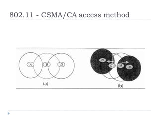
- 23. 802.11 - CSMA/CA access method
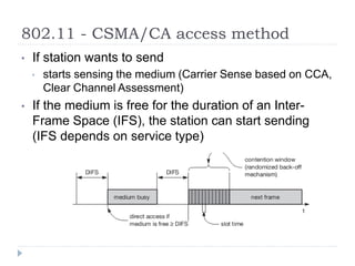
- 24. 802.11 - CSMA/CA access method ŌĆó If station wants to send ŌĆó starts sensing the medium (Carrier Sense based on CCA, Clear Channel Assessment) ŌĆó If the medium is free for the duration of an Inter- Frame Space (IFS), the station can start sending (IFS depends on service type)
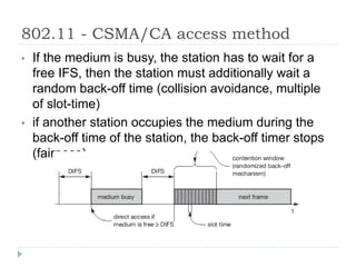
- 25. 802.11 - CSMA/CA access method ŌĆó If the medium is busy, the station has to wait for a free IFS, then the station must additionally wait a random back-off time (collision avoidance, multiple of slot-time) ŌĆó if another station occupies the medium during the back-off time of the station, the back-off timer stops (fairness)
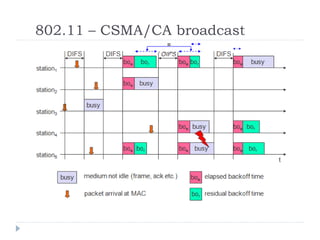
- 26. 802.11 ŌĆō CSMA/CA broadcast
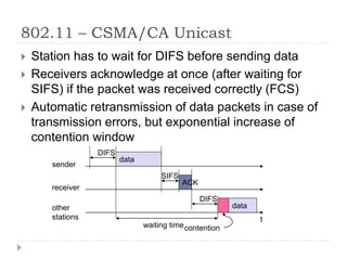
- 27. 802.11 ŌĆō CSMA/CA Unicast ’üĮ Station has to wait for DIFS before sending data ’üĮ Receivers acknowledge at once (after waiting for SIFS) if the packet was received correctly (FCS) ’üĮ Automatic retransmission of data packets in case of transmission errors, but exponential increase of contention window t SIFS DIFS data ACK waiting time other stations receiver sender data DIFS contention
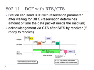
- 28. 802.11 ŌĆō DCF with RTS/CTS ’üĮ Station can send RTS with reservation parameter after waiting for DIFS (reservation determines amount of time the data packet needs the medium) ’üĮ acknowledgement via CTS after SIFS by receiver (if ready to receive)
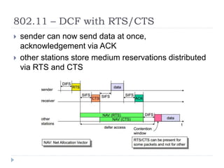
- 29. 802.11 ŌĆō DCF with RTS/CTS ’üĮ sender can now send data at once, acknowledgement via ACK ’üĮ other stations store medium reservations distributed via RTS and CTS
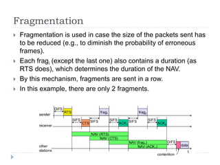
- 30. Fragmentation ’üĮ Fragmentation is used in case the size of the packets sent has to be reduced (e.g., to diminish the probability of erroneous frames). ’üĮ Each fragi (except the last one) also contains a duration (as RTS does), which determines the duration of the NAV. ’üĮ By this mechanism, fragments are sent in a row. ’üĮ In this example, there are only 2 fragments.
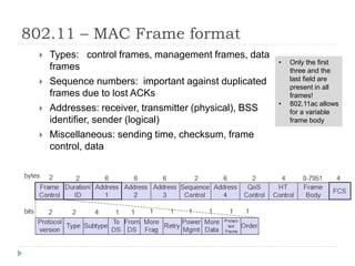
- 31. 802.11 ŌĆō MAC Frame format ’üĮ Types: control frames, management frames, data frames ’üĮ Sequence numbers: important against duplicated frames due to lost ACKs ’üĮ Addresses: receiver, transmitter (physical), BSS identifier, sender (logical) ’üĮ Miscellaneous: sending time, checksum, frame control, data ŌĆó Only the first three and the last field are present in all frames! ŌĆó 802.11ac allows for a variable frame body
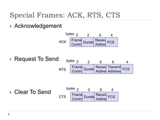
- 32. Special Frames: ACK, RTS, CTS ’üĮ Acknowledgement ’üĮ Request To Send ’üĮ Clear To Send Frame Control Duration Receiver Address Transmitter Address FCS 2 2 6 6 4 bytes Frame Control Duration Receiver Address FCS 2 2 6 4 bytes Frame Control Duration Receiver Address FCS 2 2 6 4 bytes ACK RTS CTS
- 33. Bluetooth ’üĮ Basic idea ’üĮ local area networks with a very limited coverage and without the need for an infrastructure. ’üĮ Interconnecting computer and peripherals, handheld devices, PDAs, cell phones ’üĮ Embedded in other devices ’üĮ Data transfer at a speed of about 720 Kbps within 50 meters (150 feet) of range or beyond through walls, clothing and even luggage bags.
- 34. Bluetooth Protocol - Overview ’üĮ Uses the master and slave relationship ’üĮ Master and slaves together form a Piconet when master allows slaves to talk ’üĮ Up to seven ŌĆśslaveŌĆÖ devices can be set to communicate with a ŌĆśmasterŌĆÖ in a Piconet ŌĆō Why? ’üĮ Scatternet is formed when several of piconets are linked together to form a larger network in an ad hoc manner. ’üĮ Bluetooth operates on 79 channels in the 2.4 GHz band with 1 MHz carrier spacing. ’üĮ 2.402 GHz to 2.480 GHz
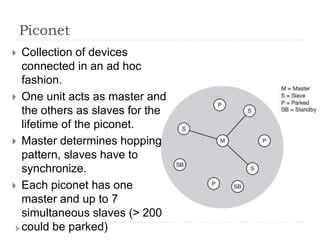
- 35. Piconet ’üĮ Collection of devices connected in an ad hoc fashion. ’üĮ One unit acts as master and the others as slaves for the lifetime of the piconet. ’üĮ Master determines hopping pattern, slaves have to synchronize. ’üĮ Each piconet has one master and up to 7 simultaneous slaves (> 200 could be parked)
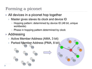
- 36. Forming a piconet ’üĮ All devices in a piconet hop together ’üĮ Master gives slaves its clock and device ID ’üĮ Hopping pattern: determined by device ID (48 bit, unique worldwide) ’üĮ Phase in hopping pattern determined by clock ’üĮ Addressing ’üĮ Active Member Address (AMA, 3 bit) ’üĮ Parked Member Address (PMA, 8 bit)
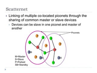
- 37. Scatternet ’üĮ Linking of multiple co-located piconets through the sharing of common master or slave devices ’üĮ Devices can be slave in one piconet and master of another M=Master S=Slave P=Parked SB=Standby M S P SB S S P P SB M S S P SB Piconets
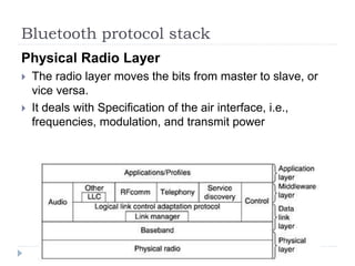
- 38. Bluetooth protocol stack Physical Radio Layer ’üĮ The radio layer moves the bits from master to slave, or vice versa. ’üĮ It deals with Specification of the air interface, i.e., frequencies, modulation, and transmit power
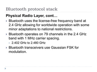
- 39. Bluetooth protocol stack Physical Radio Layer, contŌĆ” ’üĮ Bluetooth uses the license-free frequency band at 2.4 GHz allowing for worldwide operation with some minor adaptations to national restrictions. ’üĮ Bluetooth operates on 79 channels in the 2.4 GHz band with 1 MHz carrier spacing. ’üĮ 2.402 GHz to 2.480 GHz ’üĮ Bluetooth transceivers use Gaussian FSK for modulation.
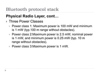
- 40. Bluetooth protocol stack Physical Radio Layer, contŌĆ” ’üĮ Three Power Classes ’üĮ Power class 1: Maximum power is 100 mW and minimum is 1 mW (typ.100 m range without obstacles). ’üĮ Power class 2:Maximum power is 2.5 mW, nominal power is 1 mW, and minimum power is 0.25 mW (typ. 10 m range without obstacles). ’üĮ Power class 3:Maximum power is 1 mW.
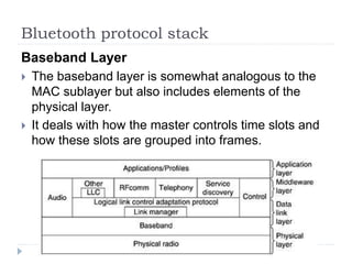
- 41. Bluetooth protocol stack Baseband Layer ’üĮ The baseband layer is somewhat analogous to the MAC sublayer but also includes elements of the physical layer. ’üĮ It deals with how the master controls time slots and how these slots are grouped into frames.
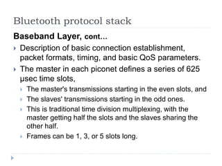
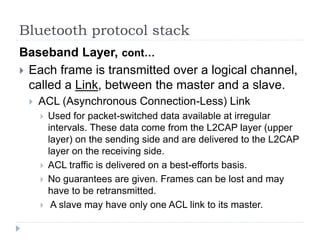
- 42. Bluetooth protocol stack Baseband Layer, contŌĆ” ’üĮ Description of basic connection establishment, packet formats, timing, and basic QoS parameters. ’üĮ The master in each piconet defines a series of 625 ┬Ąsec time slots, ’üĮ The master's transmissions starting in the even slots, and ’üĮ The slaves' transmissions starting in the odd ones. ’üĮ This is traditional time division multiplexing, with the master getting half the slots and the slaves sharing the other half. ’üĮ Frames can be 1, 3, or 5 slots long.
- 43. Bluetooth protocol stack Baseband Layer, contŌĆ” ’üĮ Each frame is transmitted over a logical channel, called a Link, between the master and a slave. ’üĮ ACL (Asynchronous Connection-Less) Link ’üĮ Used for packet-switched data available at irregular intervals. These data come from the L2CAP layer (upper layer) on the sending side and are delivered to the L2CAP layer on the receiving side. ’üĮ ACL traffic is delivered on a best-efforts basis. ’üĮ No guarantees are given. Frames can be lost and may have to be retransmitted. ’üĮ A slave may have only one ACL link to its master.
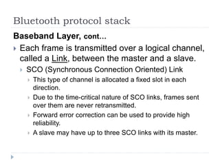
- 44. Bluetooth protocol stack Baseband Layer, contŌĆ” ’üĮ Each frame is transmitted over a logical channel, called a Link, between the master and a slave. ’üĮ SCO (Synchronous Connection Oriented) Link ’üĮ This type of channel is allocated a fixed slot in each direction. ’üĮ Due to the time-critical nature of SCO links, frames sent over them are never retransmitted. ’üĮ Forward error correction can be used to provide high reliability. ’üĮ A slave may have up to three SCO links with its master.
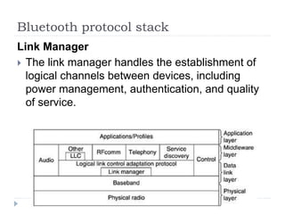
- 45. Bluetooth protocol stack Link Manager ’üĮ The link manager handles the establishment of logical channels between devices, including power management, authentication, and quality of service.
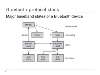
- 46. Bluetooth protocol stack Major baseband states of a Bluetooth device
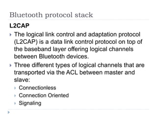
- 47. Bluetooth protocol stack L2CAP ’üĮ The logical link control and adaptation protocol (L2CAP) is a data link control protocol on top of the baseband layer offering logical channels between Bluetooth devices. ’üĮ Three different types of logical channels that are transported via the ACL between master and slave: ’üĮ Connectionless ’üĮ Connection Oriented ’üĮ Signaling
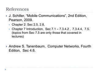
- 48. References ’üĮ J. Schiller, ŌĆ£Mobile CommunicationsŌĆØ, 2nd Edition, Pearson, 2009. ’üĮ Chapter 2: Sec 2.5, 2.8, ’üĮ Chapter 7 Introduction, Sec 7.1 ŌĆō 7.3.4.2 , 7.3.4.4, 7.5. (topics from Sec 7.5 are only those that covered in lectures) ’üĮ Andrew S. Tanenbaum, Computer Networks, Fourth Edition, Sec 4.6.
Editor's Notes
- #3: Mobile Communications 2002
- #4: Mobile Communications 2002
- #5: Mobile Communications 2002
- #6: Mobile Communications 2002
- #8: Mobile Communications 2002
- #9: Mobile Communications 2002
- #10: Mobile Communications 2002
- #11: Mobile Communications 2002
- #12: Mobile Communications 2002
- #13: Mobile Communications 2002
- #14: Mobile Communications 2002
- #25: Mobile Communications 2002
- #26: Mobile Communications 2002
- #27: Mobile Communications 2002
- #28: Mobile Communications 2002
- #29: Mobile Communications 2002
- #30: Mobile Communications 2002
- #31: Mobile Communications 2002
- #32: Mobile Communications 2002
- #33: Mobile Communications 2002
- #34: Mobile Communications 2002
- #36: Mobile Communications 2002
- #37: Mobile Communications 2002
- #38: Mobile Communications 2002