The Karnaugh map method provides a graphical way to simplify logic equations or convert truth tables into logic circuits. It arranges variables in a grid so that adjacent squares differ in only one variable. Loops of adjacent 1s can then be identified to eliminate variables from the logic expression. Larger loops eliminate more variables - pairs eliminate one variable, quads eliminate two variables, and octets eliminate three variables. The method is demonstrated through examples of constructing Karnaugh maps from truth tables and simplifying the resulting logic expressions through looping.
This document provides an overview of Boolean algebra and logic simplification. It defines Boolean operations and variables, lists laws and rules of Boolean algebra including De Morgan's theorems. It also explains standard forms of Boolean expressions, truth tables, and how to use Karnaugh maps to minimize logic expressions in sum of products or product of sums form. Karnaugh maps allow grouping variables to simplify expressions for 2, 3, 4 or more variables.
Karnaugh maps are a graphical technique used to simplify Boolean logic equations. They represent truth tables in a two-dimensional layout where physically adjacent cells imply logical adjacency. This adjacency allows common terms to be factored out to minimize logic expressions. Karnaugh maps are most commonly used to manually minimize logic with up to four variables into sum-of-products or product-of-sums form.
This document discusses Karnaugh maps (K-maps), which are a tool for simplifying Boolean expressions into their minimum sum-of-products (SOP) or product-of-sums (POS) forms. It explains how to map standard and non-standard SOP expressions onto K-maps by placing 1s in the cells corresponding to the terms. Groups of adjacent 1s can then be identified to find the minimum SOP expression. The same process applies to POS expressions, except 0s are placed on the map instead of 1s. Examples are provided to demonstrate how to group cells and determine the minimum expressions from K-maps.
Boolean algebra deals with logical operations on binary variables that have two possible values, typically represented as 1 and 0. George Boole first introduced Boolean algebra in 1854. Boolean algebra uses logic gates like AND, OR, and NOT as basic building blocks. Positive logic represents 1 as high and 0 as low, while negative logic uses the opposite. Boolean algebra laws and Karnaugh maps are used to simplify logical expressions. Don't care conditions allow for groupings in K-maps that further reduce expressions.
Karnaugh maps are a graphical method used to minimize logic functions. They arrange the minterms of a function in a grid based on the number of variables. Groupings of adjacent 1s in the map correspond to simplified logic terms. The largest possible groupings are used to find a minimum logic expression for the function. Don't cares can also be grouped and treated as 0s or 1s to further simplify expressions.
The document provides information about digital logic circuits including definitions of binary logic, steps for binary to decimal and hexadecimal conversions, classification of binary codes, logic gates, combinational logic circuits like multiplexers, decoders, encoders, and comparators. It also includes properties of Boolean algebra and methods for minimizing Boolean functions using Karnaugh maps and Quine-McCluskey method. Various problems are given involving binary arithmetic, logic gate implementations, Boolean expressions and their simplification.
The document discusses combinational logic circuits. It covers sum-of-products and product-of-sums forms for representing logic functions. Methods for analyzing and simplifying logic circuits are presented, including Boolean algebra, Karnaugh maps, and deriving truth tables from logic diagrams. Examples of common logic circuits like adders, decoders, and converters are provided along with steps for designing combinational logic circuits.
This document discusses combinational logic circuits. It begins by defining combinational circuits as those with no storage or feedback, so their outputs depend only on current inputs. It then provides the steps to analyze a combinational circuit by labeling outputs and determining Boolean functions until reaching the outputs. Design procedures are also outlined. Specific combinational circuits discussed include half and full adders used for binary addition, with their truth tables and logic implementations shown. Subtraction using borrow is also briefly introduced.
The document describes the Karnaugh map method for simplifying Boolean logic expressions. K-maps allow logic variables and their combinations to be visualized graphically. Cells in the K-map correspond to minterms in the truth table. Adjacent cells that differ in only one variable can be grouped to simplify the logic expression. Larger groupings eliminate more variables. Examples show how to construct K-maps for up to four variables and extract simplified logic expressions from the groupings.
Digital logic circuits important question and answers for 5 unitsLekashri Subramanian
油
This document provides information about digital logic circuits and binary operations. It includes definitions of key terms like registers, register transfer, binary logic, logic gates, and parity bits. It also covers operations like subtraction using 2's and 1's complements, and reducing Boolean expressions using De Morgan's theorems, duality properties, and canonical forms.
This document provides an overview of digital electronics and Boolean algebra topics, including:
- Boolean algebra deals with binary variables and logical operations. It originated from George Boole's 1854 book.
- Logic gates are basic building blocks of digital systems. Common logic gates include AND, OR, NOT, NAND, NOR gates.
- Boolean laws like commutative, associative, distributive, De Morgan's theorems are used to simplify logic expressions.
- Karnaugh maps are used to minimize logic expressions into sum of products or product of sums form. Don't care conditions allow for further simplification.
- Universal gates like NAND and NOR can be used to construct all other logic gates
This document provides an overview of Boolean algebra, which describes logical relations and operations in digital circuits. It discusses:
1) George Boole's rules that describe logical propositions as either true or false, which can represent digital circuit states of 1 or 0.
2) Basic Boolean operations like AND, OR, and NOT and how they are represented by logic gates. Truth tables show all possible input/output combinations for each gate.
3) Laws of Boolean algebra like commutativity, association, distribution, and others. Karnaugh maps provide a way to simplify Boolean expressions into sum-of-products form.
1. In Boolean algebra, a variable represents a logical quantity that can have a value of 1 or 0. Operations like addition and multiplication represent logical OR and AND operations.
2. Karnaugh maps are used to simplify Boolean expressions by grouping variables and eliminating variables that change between adjacent cells. This groups variables to find the minimum logic expression.
3. Hardware description languages like VHDL and Verilog allow digital designs to be described and implemented using code. VHDL uses entities to describe inputs and outputs, and architectures to describe logic, while Verilog uses modules.
Karnaugh maps provide an alternative way to simplify logic circuits by visually grouping adjacent cells containing 1's and 0's in a map based on the truth table. The document provides examples of 2, 3, and 4 variable Karnaugh maps and explains how to construct the maps from truth tables and simplify logic functions into minimal Boolean expressions.
The document discusses Karnaugh maps and their use in minimizing Boolean functions. Karnaugh maps arrange variables in a grid and use 1s and 0s to represent truth table outputs. Adjacent 1s that differ in only one variable can be combined to simplify the Boolean expression. Larger groups like quads and octets allow eliminating more variables. Karnaugh maps provide a visual way to minimize functions through identifying and combining adjacent terms.
Boolean algebra is used to analyze and simplify digital circuits using binary numbers 0 and 1. It defines operations like complement, OR, AND and rules like commutative, distributive, inversion and De Morgan's theorems. Karnaugh maps provide a graphical way to minimize logic functions with up to 6 variables into sums of products form. Several examples show how to apply Boolean algebra rules and theorems as well as construct and simplify functions using Karnaugh maps.
Karnaugh maps provide an alternative way to simplify logic circuits compared to Boolean algebra. A Karnaugh map arranges the 1s and 0s from a truth table into cells based on the number of variables. Adjacent cells containing 1s are grouped to find simplified logic expressions in a visual manner. Karnaugh maps are commonly used for 2, 3, or 4 variable problems by arranging the cells accordingly. They allow the logic relationships between variables to be visualized in order to minimize Boolean expressions.
This document discusses combinational circuits and their components. It begins by defining combinational circuits as circuits whose outputs only depend on the current inputs, not previous states. It then discusses Karnaugh maps, which are used to simplify Boolean expressions through grouping variables. Various types of combinational components are covered, including adders, subtractors, and their half and full versions. Finally, it provides the procedures for designing, analyzing, and obtaining truth tables from combinational circuits.
The document discusses Boolean algebra and logic gates. It defines logic gates, explains their operations, and provides their logic symbols and truth tables. The types of logic gates covered are AND, OR, NOT, NOR, NAND, XOR, and XNOR. It also discusses sequential logic circuits like flip-flops, providing details on SR, JK, T, and D flip-flops including how to build them using logic gates. Additional topics covered include the difference between combinational and sequential logic circuits, Boolean theorems, sum-of-products and product-of-sums expressions, and the Karnaugh map method for simplifying logic expressions.
The document discusses Karnaugh maps (K-maps), which are a tool for representing and simplifying Boolean functions with up to six variables. K-maps arrange the variables in a grid according to their binary values. Adjacent cells that differ in only one variable can be combined to simplify the function by eliminating that variable. The document provides examples of using K-maps to minimize Boolean functions in sum of products and product of sums form. It also discusses techniques like combining cells into the largest groups possible and handling don't-care conditions to further simplify expressions.
Transistors can be used as switches in logic circuits to perform operations like AND, OR, and XOR.
AND logic returns 1 only if both inputs are 1. OR logic returns 1 if either or both inputs are 1.
XOR (exclusive OR) returns 1 if only one input is 1, but not both.
Binary numbers use a base-2 system of 0 and 1 to represent values, with place values increasing in powers of two from right to left. Decimal numbers can be converted to binary by repeatedly dividing the number by two and noting the remainders.
This document provides an overview of using Karnaugh maps to minimize Boolean expressions. It begins with an example of minimizing a 3-variable expression using both algebraic manipulation and a Karnaugh map. Key concepts discussed include grouping adjacent 1s on the map, where adjacency includes horizontal, vertical, and diagonal neighbors. Larger groups that encompass both values of a variable eliminate that term from the minimized expression. The document then demonstrates 4-variable and don't-care maps. It concludes with practice problems for the reader to write minimized expressions and truth tables for additional maps.
How to Build a Maze Solving Robot Using ArduinoCircuitDigest
油
Learn how to make an Arduino-powered robot that can navigate mazes on its own using IR sensors and "Hand on the wall" algorithm.
This step-by-step guide will show you how to build your own maze-solving robot using Arduino UNO, three IR sensors, and basic components that you can easily find in your local electronics shop.
Preface: The ReGenX Generator innovation operates with a US Patented Frequency Dependent Load Current Delay which delays the creation and storage of created Electromagnetic Field Energy around the exterior of the generator coil. The result is the created and Time Delayed Electromagnetic Field Energy performs any magnitude of Positive Electro-Mechanical Work at infinite efficiency on the generator's Rotating Magnetic Field, increasing its Kinetic Energy and increasing the Kinetic Energy of an EV or ICE Vehicle to any magnitude without requiring any Externally Supplied Input Energy. In Electricity Generation applications the ReGenX Generator innovation now allows all electricity to be generated at infinite efficiency requiring zero Input Energy, zero Input Energy Cost, while producing zero Greenhouse Gas Emissions, zero Air Pollution and zero Nuclear Waste during the Electricity Generation Phase. In Electric Motor operation the ReGen-X Quantum Motor now allows any magnitude of Work to be performed with zero Electric Input Energy.
Demonstration Protocol: The demonstration protocol involves three prototypes;
1. Protytpe #1, demonstrates the ReGenX Generator's Load Current Time Delay when compared to the instantaneous Load Current Sine Wave for a Conventional Generator Coil.
2. In the Conventional Faraday Generator operation the created Electromagnetic Field Energy performs Negative Work at infinite efficiency and it reduces the Kinetic Energy of the system.
3. The Magnitude of the Negative Work / System Kinetic Energy Reduction (in Joules) is equal to the Magnitude of the created Electromagnetic Field Energy (also in Joules).
4. When the Conventional Faraday Generator is placed On-Load, Negative Work is performed and the speed of the system decreases according to Lenz's Law of Induction.
5. In order to maintain the System Speed and the Electric Power magnitude to the Loads, additional Input Power must be supplied to the Prime Mover and additional Mechanical Input Power must be supplied to the Generator's Drive Shaft.
6. For example, if 100 Watts of Electric Power is delivered to the Load by the Faraday Generator, an additional >100 Watts of Mechanical Input Power must be supplied to the Generator's Drive Shaft by the Prime Mover.
7. If 1 MW of Electric Power is delivered to the Load by the Faraday Generator, an additional >1 MW Watts of Mechanical Input Power must be supplied to the Generator's Drive Shaft by the Prime Mover.
8. Generally speaking the ratio is 2 Watts of Mechanical Input Power to every 1 Watt of Electric Output Power generated.
9. The increase in Drive Shaft Mechanical Input Power is provided by the Prime Mover and the Input Energy Source which powers the Prime Mover.
10. In the Heins ReGenX Generator operation the created and Time Delayed Electromagnetic Field Energy performs Positive Work at infinite efficiency and it increases the Kinetic Energy of the system.
This PPT covers the index and engineering properties of soil. It includes details on index properties, along with their methods of determination. Various important terms related to soil behavior are explained in detail. The presentation also outlines the experimental procedures for determining soil properties such as water content, specific gravity, plastic limit, and liquid limit, along with the necessary calculations and graph plotting. Additionally, it provides insights to understand the importance of these properties in geotechnical engineering applications.
Optimization of Cumulative Energy, Exergy Consumption and Environmental Life ...J. Agricultural Machinery
油
Optimal use of resources, including energy, is one of the most important principles in modern and sustainable agricultural systems. Exergy analysis and life cycle assessment were used to study the efficient use of inputs, energy consumption reduction, and various environmental effects in the corn production system in Lorestan province, Iran. The required data were collected from farmers in Lorestan province using random sampling. The Cobb-Douglas equation and data envelopment analysis were utilized for modeling and optimizing cumulative energy and exergy consumption (CEnC and CExC) and devising strategies to mitigate the environmental impacts of corn production. The Cobb-Douglas equation results revealed that electricity, diesel fuel, and N-fertilizer were the major contributors to CExC in the corn production system. According to the Data Envelopment Analysis (DEA) results, the average efficiency of all farms in terms of CExC was 94.7% in the CCR model and 97.8% in the BCC model. Furthermore, the results indicated that there was excessive consumption of inputs, particularly potassium and phosphate fertilizers. By adopting more suitable methods based on DEA of efficient farmers, it was possible to save 6.47, 10.42, 7.40, 13.32, 31.29, 3.25, and 6.78% in the exergy consumption of diesel fuel, electricity, machinery, chemical fertilizers, biocides, seeds, and irrigation, respectively.
Preface: The ReGenX Generator innovation operates with a US Patented Frequency Dependent Load
Current Delay which delays the creation and storage of created Electromagnetic Field Energy around
the exterior of the generator coil. The result is the created and Time Delayed Electromagnetic Field
Energy performs any magnitude of Positive Electro-Mechanical Work at infinite efficiency on the
generator's Rotating Magnetic Field, increasing its Kinetic Energy and increasing the Kinetic Energy of
an EV or ICE Vehicle to any magnitude without requiring any Externally Supplied Input Energy. In
Electricity Generation applications the ReGenX Generator innovation now allows all electricity to be
generated at infinite efficiency requiring zero Input Energy, zero Input Energy Cost, while producing
zero Greenhouse Gas Emissions, zero Air Pollution and zero Nuclear Waste during the Electricity
Generation Phase. In Electric Motor operation the ReGen-X Quantum Motor now allows any
magnitude of Work to be performed with zero Electric Input Energy.
Demonstration Protocol: The demonstration protocol involves three prototypes;
1. Protytpe #1, demonstrates the ReGenX Generator's Load Current Time Delay when compared
to the instantaneous Load Current Sine Wave for a Conventional Generator Coil.
2. In the Conventional Faraday Generator operation the created Electromagnetic Field Energy
performs Negative Work at infinite efficiency and it reduces the Kinetic Energy of the system.
3. The Magnitude of the Negative Work / System Kinetic Energy Reduction (in Joules) is equal to
the Magnitude of the created Electromagnetic Field Energy (also in Joules).
4. When the Conventional Faraday Generator is placed On-Load, Negative Work is performed and
the speed of the system decreases according to Lenz's Law of Induction.
5. In order to maintain the System Speed and the Electric Power magnitude to the Loads,
additional Input Power must be supplied to the Prime Mover and additional Mechanical Input
Power must be supplied to the Generator's Drive Shaft.
6. For example, if 100 Watts of Electric Power is delivered to the Load by the Faraday Generator,
an additional >100 Watts of Mechanical Input Power must be supplied to the Generator's Drive
Shaft by the Prime Mover.
7. If 1 MW of Electric Power is delivered to the Load by the Faraday Generator, an additional >1
MW Watts of Mechanical Input Power must be supplied to the Generator's Drive Shaft by the
Prime Mover.
8. Generally speaking the ratio is 2 Watts of Mechanical Input Power to every 1 Watt of Electric
Output Power generated.
9. The increase in Drive Shaft Mechanical Input Power is provided by the Prime Mover and the
Input Energy Source which powers the Prime Mover.
10. In the Heins ReGenX Generator operation the created and Time Delayed Electromagnetic Field
Energy performs Positive Work at infinite efficiency and it increases the Kinetic Energy of the
system.
Engineering at Lovely Professional University (LPU).pdfSona
油
LPUs engineering programs provide students with the skills and knowledge to excel in the rapidly evolving tech industry, ensuring a bright and successful future. With world-class infrastructure, top-tier placements, and global exposure, LPU stands as a premier destination for aspiring engineers.
This presentation provides an in-depth analysis of structural quality control in the KRP 401600 section of the Copper Processing Plant-3 (MOF-3) in Uzbekistan. As a Structural QA/QC Inspector, I have identified critical welding defects, alignment issues, bolting problems, and joint fit-up concerns.
Key topics covered:
Common Structural Defects Welding porosity, misalignment, bolting errors, and more.
Root Cause Analysis Understanding why these defects occur.
Corrective & Preventive Actions Effective solutions to improve quality.
Team Responsibilities Roles of supervisors, welders, fitters, and QC inspectors.
Inspection & Quality Control Enhancements Advanced techniques for defect detection.
Applicable Standards: GOST, KMK, SNK Ensuring compliance with international quality benchmarks.
This presentation is a must-watch for:
QA/QC Inspectors, Structural Engineers, Welding Inspectors, and Project Managers in the construction & oil & gas industries.
Professionals looking to improve quality control processes in large-scale industrial projects.
Download & share your thoughts! Let's discuss best practices for enhancing structural integrity in industrial projects.
Categories:
Engineering
Construction
Quality Control
Welding Inspection
Project Management
Tags:
#QAQC #StructuralInspection #WeldingDefects #BoltingIssues #ConstructionQuality #Engineering #GOSTStandards #WeldingInspection #QualityControl #ProjectManagement #MOF3 #CopperProcessing #StructuralEngineering #NDT #OilAndGas
1. KARNAUGH MAP METHOD
KARNAUGH MAP METHOD
The Karnaugh map is a graphical device used to simplify a logic
equation or to convert a truth table to its corresponding logic
circuit in a simple, orderly process.
Although a Karnaugh map (henceforth abbreviated K map) can
be used for problems involving any number of input variables,
its practical usefulness is limited to six variables.
The following discussion will be limited to problems with up to
four inputs, since even five-and six- input problems are too
involved and are best done by a computer program.
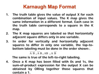
2. Karnaugh Map Format
Karnaugh Map Format
1. The truth table gives the value of output X for each
combination of input values. The K map gives the
same information in a different format. Each case in
the truth table corresponds to a square in the K
map.
2. The K map squares are labeled so that horizontally
adjacent square differs only in one variable.
3. In order for vertically and horizontally adjacent
squares to differ in only one variable, the top-to-
bottom labeling must be done in the order shown-.
The same is true of the left-to-right labeling.
4. Once a K map has been filled with 0s and 1s, the
sum-of-product expression for the output X can be
obtained by ORing together those squares that
contain a 1.
B
A
AB
B
A
B
A ,
,
,
3. The expression for output X can be simplified by
properly combining those squares in the K map
which contain 1s.
The process for combining these 1s is called
looping.
Looping
Looping
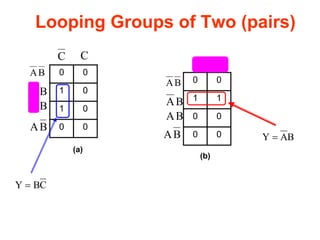
4. Looping Groups of Two (pairs)
0 0
1 0
1 0
0 0
C C
B
A
B
A
B
A
B
A
0 0
1 1
0 0
0 0
C C
B
A
B
A
B
A
B
A
C
B
Y =
B
A
Y =
(a)
(b)
5. Looping Groups of Two (pairs) (Continued)
1 0
0 0
0 0
1 0
C C
B
A
B
A
B
A
B
A
C
B
Y =
(c)
Looping a pair of adjacent 1s in a K map eliminates the variable
that appears in complemented and uncomplemented form.
6. Redundant Looping
Redundant Looping
0 0 1 1
0 0 0 0
0 0 0 0
1 0 0 1
B
A
B
A
B
A
B
A
D
C D
C D
C D
C
D
B
A
C
B
A
D
C
B Redundant Looping
D
B
A
C
B
A
Y +
=
D
C
B
D
B
A
C
B
A
Y +
+
=
NOT
NOT
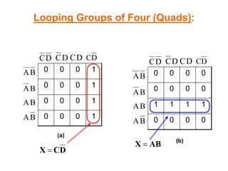
7. Looping Groups of Four (Quads):
0 0 0 1
0 0 0 1
0 0 0 1
0 0 0 1
B
A
B
A
B
A
B
A
D
C D
C D
C D
C
0 0 0 0
0 0 0 0
1 1 1 1
0 0 0 0
B
A
B
A
B
A
B
A
D
C D
C D
C D
C
(a)
(b)
D
C
X =
AB
X =
8. Looping Groups of Four (Quads) (continued)
0 0 0 0
0 1 1 0
0 1 1 0
0 0 0 0
B
A
B
A
B
A
B
A
D
C D
C D
C D
C
0 0 0 0
0 0 0 0
1 0 0 1
1 0 0 1
B
A
B
A
B
A
B
A
D
C D
C D
C D
C
(c) (d)
BD
=
X D
A
X =
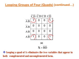
9. Looping Groups of Four (Quads) (continued)
1 0 0 1
0 0 0 0
0 0 0 0
1 0 0 1
B
A
B
A
B
A
B
A
D
C D
C D
C D
C
(e)
D
B
=
X
Looping a quad of 1s eliminates the two variables that appear i
Looping a quad of 1s eliminates the two variables that appear in
n
both complemented and uncomplemented form.
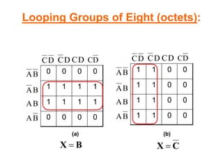
10. Looping Groups of Eight (octets):
0 0 0 0
1 1 1 1
1 1 1 1
0 0 0 0
B
A
B
A
B
A
B
A
D
C D
C D
C D
C
1 1 0 0
1 1 0 0
1 1 0 0
1 1 0 0
B
A
B
A
B
A
B
A
D
C D
C D
C D
C
B
X =
(a) (b)
C
X =
11. Looping Groups of Eight (Octets) (continued)
1 1 1 1
0 0 0 0
0 0 0 0
1 1 1 1
B
A
B
A
B
A
B
A
D
C D
C D
C D
C
1 0 0 1
1 0 0 1
1 0 0 1
1 0 0 1
B
A
B
A
B
A
B
A
D
C D
C D
C D
C
(c) (d)
B
Y = D
Y =
Looping an octet of 1s eliminates the three variables that appea
Looping an octet of 1s eliminates the three variables that appear
r
in both complemented and uncomplemented form.
12. Rule for loops of any size
Rule for loops of any size
We can summarize the rule for loops of any size:
When a variable appears in both complemented and
uncomplemented form within a loop, that variable is eliminated
from the expression.
Variables that are the same for all squares of the loop must appear
in the final expression.
It should be clear that a larger loop of 1s eliminates more
variables. To be exact, a loop of two eliminates one variable, a loop
of four eliminates two, and a loop of eight eliminates three.
13. Complete Simplification Process
Complete Simplification Process
1. Construct the K map and place 1s in those squares corresponding to
the 1s in the truth table. Place 0s in the other squares.
2. Examine the map for adjacent 1s and loop those 1s, which are not
adjacent to any other 1s. These are called isolated 1s.
3. Next, look for those 1s, which are adjacent to only one other 1. Loop
any pair containing such a 1.
4. Loop any octet even it contains some 1s that have already been
looped.
5. Loop any quad that contains one or more 1s, which have not already
been looped, is making sure to use the minimum number of loops.
6. Loop any pairs necessary to include any 1s that have not yet been
looped, making sure to use the minimum number of loops.
7. Form the OR sum of all the terms generated by each loop.
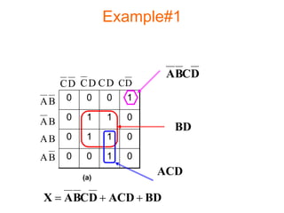
14. Example#1
0 0 0 1
0 1 1 0
0 1 1 0
0 0 1 0
B
A
B
A
B
A
B
A
D
C D
C D
C D
C
(a)
ACD
BD
D
C
B
A
BD
ACD
D
C
B
A
X +
+
=
15. Example#2
0 1 0 0
0 1 1 1
0 0 0 1
1 1 0 1
B
A
B
A
B
A
B
A
D
C D
C D
C D
C
D
C
A
BC
A
D
AC
C
B
A
C
B
A
D
AC
BC
A
D
C
A
X +
+
+
=
Option #1
Option #1
16. Example#
0 1 0 0
0 1 1 1
0 0 0 1
1 1 0 1
B
A
B
A
B
A
B
A
D
C D
C D
C D
C
D
C
B
BD
A
D
BC
D
B
A
D
B
A
D
BC
BD
A
D
C
B
X +
+
+
=
Option # 2
Option # 2
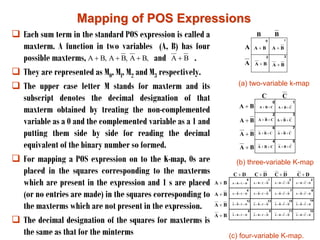
17. Mapping of POS Expressions
Mapping of POS Expressions
Each sum term in the standard POS expression is called a
maxterm. A function in two variables (A, B) has four
possible maxterms, and .
They are represented as M0, Ml, M2 and M3 respectively.
The upper case letter M stands for maxterm and its
subscript denotes the decimal designation of that
maxterm obtained by treating the non-complemented
variable as a 0 and the complemented variable as a 1 and
putting them side by side for reading the decimal
equivalent of the binary number so formed.
For mapping a POS expression on to the K-map, 0s are
placed in the squares corresponding to the maxterms
which are present in the expression and 1 s are placed
(or no entries are made) in the squares corresponding to
the maxterms which are not present in the expression.
The decimal designation of the squares for maxterms is
the same as that for the minterms
,
B
A
,
B
A
,
B
A +
+
+ B
A +
A
B
A
B
B
A + B
A +
B
A + B
A +
B
A +
B
A +
B
A +
B
A +
C
C
C
B
A +
+
C
B
A +
+
C
B
A +
+
C
B
A +
+
C
B
A +
+
C
B
A +
+
C
B
A +
+
C
B
A +
+
B
A +
B
A +
B
A +
B
A +
D
C + D
C + D
C +
D
C +
D
C
B
A +
+
+ D
C
B
A +
+
+ D
C
B
A +
+
+ D
C
B
A +
+
+
D
C
B
A +
+
+ D
C
B
A +
+
+ D
C
B
A +
+
+ D
C
B
A +
+
+
D
C
B
A +
+
+ D
C
B
A +
+
+
D
C
B
A +
+
+
D
C
B
A +
+
+
D
C
B
A +
+
+ D
C
B
A +
+
+ D
C
B
A +
+
+
D
C
B
A +
+
+
(a) two-variable k-map
(b) three-variable K-map
(c) four-variable K-map.
18. Minimization of POS Expressions
To obtain the minimal expression in the POS form, map the
given POS expression on to the K-map and combine the
adjacent 0s into as large squares as possible.
Read the squares putting the complemented variable if its
value remains constant as a 1 and the non足complemented
variable if its value remains constant as a 0 along the entire
square (ignoring the variables which do not remain constant
throughout the square) and then write them as a sum term.
Various maxterm combinations and the corresponding
reduced expressions are shown in Figure 4.13.
A
B
A
B
A
B
A
B
B
A +
B
A +
B
A +
B
A +
C
C
B
Y =
A
Y =
A
)
C
B
(
Y +
= A
C
B +
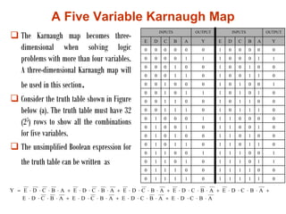
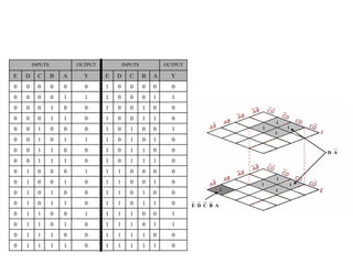
19. A Five Variable Karnaugh Map
The Karnaugh map becomes three足
dimensional when solving logic
problems with more than four variables.
A three-dimensional Karnaugh map will
be used in this section.
Consider the truth table shown in Figure
below (a). The truth table must have 32
(25) rows to show all the combinations
for five variables.
The unsimplified Boolean expression for
the truth table can be written as
A
B
C
D
E
A
B
C
D
E
A
B
C
D
E
A
B
C
D
E
A
B
C
D
E
A
B
C
D
E
A
B
C
D
E
A
B
C
D
E
A
B
C
D
E
Y
+
+
+
+
+
+
+
+
=
INPUTS OUTPUT INPUTS OUTPUT
E D C B A Y E D C B A Y
0 0 0 0 0 0 1 0 0 0 0 0
0 0 0 0 1 1 1 0 0 0 1 1
0 0 0 1 0 0 1 0 0 1 0 0
0 0 0 1 1 0 1 0 0 1 1 0
0 0 1 0 0 0 1 0 1 0 0 1
0 0 1 0 1 1 1 0 1 0 1 0
0 0 1 1 0 0 1 0 1 1 0 0
0 0 1 1 1 0 1 0 1 1 1 0
0 1 0 0 0 1 1 1 0 0 0 0
0 1 0 0 1 0 1 1 0 0 1 0
0 1 0 1 0 0 1 1 0 1 0 0
0 1 0 1 1 0 1 1 0 1 1 0
0 1 1 0 0 1 1 1 1 0 0 1
0 1 1 0 1 0 1 1 1 0 1 1
0 1 1 1 0 0 1 1 1 1 0 0
0 1 1 1 1 0 1 1 1 1 1 0
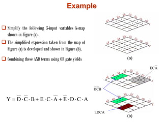
21. Example
Example
Simplify the following 5-input variables k-map
shown in Figure (a).
The simplified expression taken from the map of
Figure (a) is developed and shown in Figure (b).
Combining these AND terms using OR gate yields
A
C
D
E
A
C
E
B
C
D
Y
+
+
=
B
C
D
A
EC
DCA
E
(a)
(b)
22.
Don
Don
t Care
t Care
Conditions
Conditions
Some logic circuits can be
designed so that there are certain
input conditions for which there
are no specified output levels,
usually because these input
conditions will never occur.
In other words, there will be
certain combinations of input
levels where we dont care
whether the output is HIGH or
LOW.
This is illustrated in the truth table
of figure (a).
A
A B
B C
C Z
Z
0 0 0 0
0 0 1 0
0 1 0 0
0 1 1 X
1 0 0 X
1 0 1 1
1 1 0 1
1 1 1 1
23. 0
0 0
0
0
0 0
0
1
1 1
1
1
1 1
1
B
A
B
A
AB
B
A
C C
0
0 0
0
0
0 x
x
1
1 1
1
x
x 1
1
B
A
B
A
AB
B
A
C C
(b) (c)
Z=A
Z=A
Whenever dont care conditions occur, we have to decide
which ones to change to 0 and which to 1 to produce the best K-
map looping (i.e., the simplest expression).
This decision is not always an easy one.
25. The K-map process has several advantages over the algebraic method.
K mapping is a more orderly process with well-defined steps as compared with
the trial- and error process sometimes used in algebraic simplification.
K mapping usually requires fewer steps, especially for expressions containing
many terms, and it always produces a minimum expression.
Nevertheless, some instructors prefer the algebraic method because it requires
a thorough knowledge of Boolean algebra and is not simply a mechanical
procedure. Each method has its advantages, and though most logic designers
are adept at both, being proficient in one method is all that is necessary to
produce acceptable results.
There are other more complex techniques that designers use to minimize logic
circuits. These techniques are especially suited for circuits with large numbers
of inputs where algebraic and k-mapping methods are not feasible.
Most of these techniques can be translated into a computer program, which will
perform the minimization from input data that supply the truth table or
unsimplified expression.
Summary
Summary