


More Related Content
What's hot (20)

Viewers also liked (17)


![[Sapienza] Development of the Flight Dynamics Model of a Flying Wing Aircraft](https://cdn.slidesharecdn.com/ss_thumbnails/355a5afb-e186-4fcb-b8a5-c15a5650ca6a-160412194308-thumbnail.jpg?width=560&fit=bounds)


Similar to 4. initial climb (20)


![FLIGHT INSPECTION of CNS FACILITIES [Compatibility Mode].pdf](https://cdn.slidesharecdn.com/ss_thumbnails/flightinspectionofcnsfacilitiescompatibilitymode-230606130026-76dd62e0-thumbnail.jpg?width=560&fit=bounds)


4. initial climb
- 1. 4. INITIAL CLIMB Performance JAR 25
- 2. INITIAL CLIMB ïž Introduction ïž Climb segments ïž Climb requirements ïž Obstacle clearance ïž Departure sector ïž Reference zero ïž Flap configuration ïž Level-off height ïž Flexible takeoff ïž Extended second segment ïž Noise abatement procedures
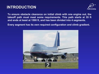
- 3. INTRODUCTION To ensure obstacle clearance on initial climb with one engine out, the takeoff path must meet some requirements. This path starts at 35 ft and ends at least at 1500 ft, and has been divided into 4 segments. Every segment has its own required configuration and climb gradient.
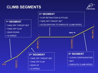
- 4. CLIMB SEGMENTS 1st SEGMENT âĒ TAKE OFF THRUST SET âĒ TAKE OFF FLAP âĒ GEAR DOWN âĒ V2 SPEED 2nd SEGMENT âĒ TAKE OFF THRUST SET âĒ TAKE OFF FLAP âĒ GEAR UP âĒ V2 SPEED 3rd SEGMENT âĒ FLAP RETRACTION ALTITUDE âĒ TAKE OFF THRUST SET âĒ ACCELERATION TO ENROUTE CLIMB SPEED 4th SEGMENT âĒ CLEAN CONFIGURATION âĒ MCT âĒ ENROUTE CLIMB SPEED GEARUP MIN400ft CLBSPEED MIN1500ft 35 ft MAX 10â
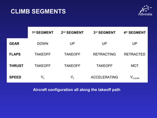
- 5. CLIMB SEGMENTS 1st SEGMENT 2nd SEGMENT 3rd SEGMENT 4th SEGMENT GEAR DOWN UP UP UP FLAPS TAKEOFF TAKEOFF RETRACTING RETRACTED THRUST TAKEOFF TAKEOFF TAKEOFF MCT SPEED V2 V2 ACCELERATING VCLEAN Aircraft configuration all along the takeoff path
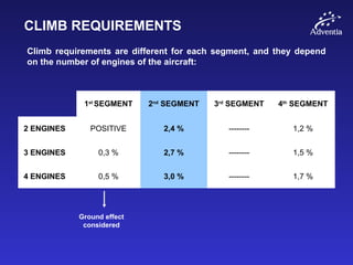
- 6. CLIMB REQUIREMENTS Climb requirements are different for each segment, and they depend on the number of engines of the aircraft: 1st SEGMENT 2nd SEGMENT 3rd SEGMENT 4th SEGMENT 2 ENGINES POSITIVE 2,4 % -------- 1,2 % 3 ENGINES 0,3 % 2,7 % -------- 1,5 % 4 ENGINES 0,5 % 3,0 % -------- 1,7 % Ground effect considered
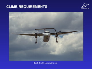
- 7. CLIMB REQUIREMENTS Dash 8 with one engine out
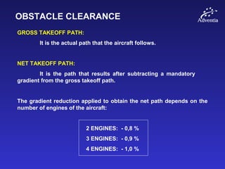
- 8. OBSTACLE CLEARANCE GROSS TAKEOFF PATH: It is the actual path that the aircraft follows. NET TAKEOFF PATH: It is the path that results after subtracting a mandatory gradient from the gross takeoff path. The gradient reduction applied to obtain the net path depends on the number of engines of the aircraft: 2 ENGINES: - 0,8 % 3 ENGINES: - 0,9 % 4 ENGINES: - 1,0 %
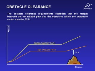
- 9. OBSTACLE CLEARANCE The obstacle clearance requirements establish that the margin between the net takeoff path and the obstacles within the departure sector must be 35 ft. Distance Altitude 35 ft GROSS TAKEOFF PATH NET TAKEOFF PATH
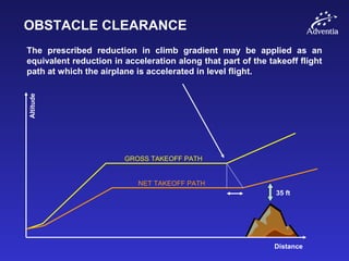
- 10. OBSTACLE CLEARANCE The prescribed reduction in climb gradient may be applied as an equivalent reduction in acceleration along that part of the takeoff flight path at which the airplane is accelerated in level flight. Distance Altitude 35 ft GROSS TAKEOFF PATH NET TAKEOFF PATH
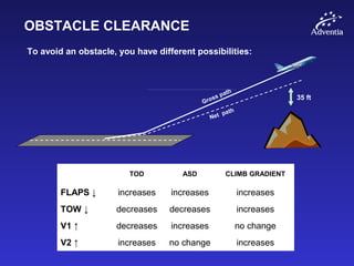
- 11. OBSTACLE CLEARANCE 35 ft Gross path Net path To avoid an obstacle, you have different possibilities: TOD ASD CLIMB GRADIENT FLAPS â increases increases increases TOW â decreases decreases increases V1 â decreases increases no change V2 â increases no change increases
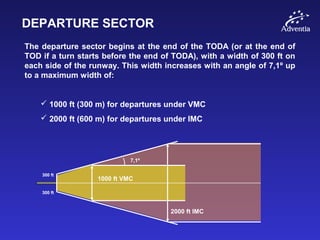
- 12. DEPARTURE SECTOR The departure sector begins at the end of the TODA (or at the end of TOD if a turn starts before the end of TODA), with a width of 300 ft on each side of the runway. This width increases with an angle of 7,1š up to a maximum width of: ïž 1000 ft (300 m) for departures under VMC ïž 2000 ft (600 m) for departures under IMC 1000 ft VMC 2000 ft IMC 300 ft 300 ft 7,1š
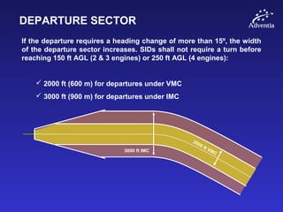
- 13. DEPARTURE SECTOR If the departure requires a heading change of more than 15š, the width of the departure sector increases. SIDs shall not require a turn before reaching 150 ft AGL (2 & 3 engines) or 250 ft AGL (4 engines): ïž 2000 ft (600 m) for departures under VMC ïž 3000 ft (900 m) for departures under IMC 2000 ft VMC3000 ft IMC
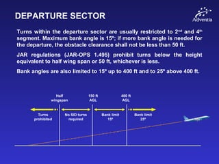
- 14. DEPARTURE SECTOR Turns within the departure sector are usually restricted to 2nd and 4th segment. Maximum bank angle is 15š; if more bank angle is needed for the departure, the obstacle clearance shall not be less than 50 ft. JAR regulations (JAR-OPS 1.495) prohibit turns below the height equivalent to half wing span or 50 ft, whichever is less. Bank angles are also limited to 15š up to 400 ft and to 25š above 400 ft. Half wingspan 150 ft AGL 400 ft AGL Turns prohibited No SID turns required Bank limit 15š Bank limit 25š
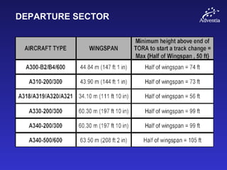
- 15. DEPARTURE SECTOR
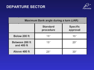
- 16. DEPARTURE SECTOR
- 17. REFERENCE ZERO The point on the ground at the end of the Takeoff Distance Required (TODR) is usually known as reference zero. Therefore, reference zero is that point where the net path reaches the screen height of 35 ft (15 ft for a wet runway) and the V2 speed, assuming critical engine failure at V1.
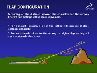
- 18. FLAP CONFIGURATION Depending on the distance between the obstacles and the runway, different flap settings will be more convenient. ïž For a distant obstacle, a lower flap setting will increase obstacle clearance capability. ïž For an obstacle close to the runway, a higher flap setting will improve obstacle clearance. FLAP 5š FLAP 15š
- 19. LEVEL-OFF HEIGHT The 3rd segment is also known as level-off height. Its minimum value is 400 ft AGL, but some airlines establish a value of 700 â 1000 ft AGL, as well as a EFP (Engine Failure Procedure). The level-off height will depend also on the Takeoff Thrust Time limitation, which is usually 5 minutes with all engines operating and 10 minutes with one engine inoperative. The Go Around thrust time limits are the same as for TO thrust.
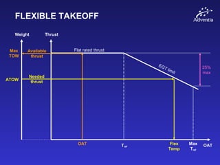
- 20. FLEXIBLE TAKEOFF When your actual takeoff weight is lower than the maximum takeoff weight, you can perform a takeoff with less than the maximum takeoff thrust, thus improving engine life and maintenance costs. To manage this thrust reduction, we use the concept of assumed or flexible temperature: The maximum OAT which would make the takeoff possible with our ATOW. The maximum allowed thrust reduction is 25%.
- 21. FLEXIBLE TAKEOFF Weight Thrust Flat rated thrust OAT EGT limit Tref OAT Available thrust Max TOW ATOW Flex Temp Max Tref 25% max Needed thrust
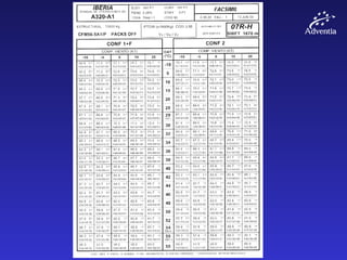
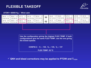
- 23. FLEXIBLE TAKEOFF ATOW = 60000 Kg / Wind calm Use the configuration giving the highest FLEX TEMP. If both configurations give the same FLEX TEMP, use the one giving the lowest speeds: CONFIG 2 : V1 â 135, VR â 135, V2 â 137 FLEX TEMP: 52 šC ïž QNH and bleed corrections may be applied to PTOW and TFLEX.
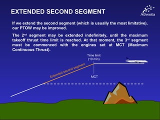
- 24. EXTENDED SECOND SEGMENT If we extend the second segment (which is usually the most limitative), our PTOW may be improved. The 2nd segment may be extended indefinitely, until the maximum takeoff thrust time limit is reached. At that moment, the 3rd segment must be commenced with the engines set at MCT (Maximum Continuous Thrust). Extended second segment MCT Time limit (10 min)
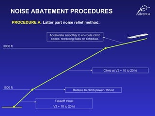
- 25. NOISE ABATEMENT PROCEDURES PROCEDURE A: Latter part noise relief method. 1500 ft 3000 ft Reduce to climb power / thrust Climb at V2 + 10 to 20 kt Accelerate smoothly to en-route climb speed, retracting flaps on schedule. Takeoff thrust V2 + 10 to 20 kt
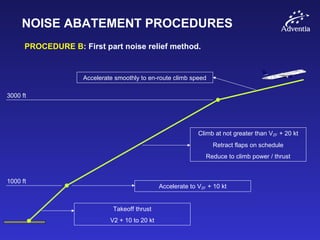
- 26. NOISE ABATEMENT PROCEDURES PROCEDURE B: First part noise relief method. 1000 ft 3000 ft Accelerate to VZF + 10 kt Climb at not greater than VZF + 20 kt Retract flaps on schedule Reduce to climb power / thrust Accelerate smoothly to en-route climb speed Takeoff thrust V2 + 10 to 20 kt