4644847.ppt
Download as PPT, PDF0 likes50 views
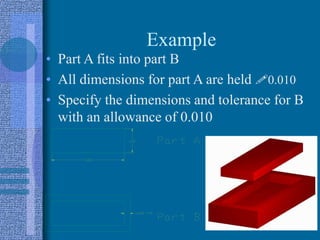
Part B Dimension: 1.500 Tolerance: +0.020/-0.010
1 of 19
Download to read offline




Recommended
Engineering -Fits and tolerances


Engineering -Fits and tolerancesSandeep Gupta
Ã˝
Basic concept of fits and tolerances and their practical use in fitment of anti friction bearings and couplings
Machine design and maintenance engineers do encounter the problem in deciding right kind of fitment while assembling various machine elements. Satisfactory functioning of a machine is very much dependent on use of right type of fitment between its various machine elements ( parts). Below is link to a presentation wherein I have tried to summarize the basic concepts of fits and tolerances and their practical use in fitment of rolling contact bearings and couplingLimits, fits and tolerances


Limits, fits and tolerancesGAURAVBHARDWAJ160
Ã˝
This document provides an overview of limits, fits, and tolerances in manufacturing. It defines key terms like basic size, tolerance, allowance, and describes different types of fits (clearance, interference, transition) and how they are specified using hole basis and shaft basis systems. It also discusses interchangeability and selective assembly, explaining how classifying components by size within their tolerance ranges enables proper assembly of mating parts from different sources.Machine Drawing PPT.ppt 2.pdf


Machine Drawing PPT.ppt 2.pdfssuseraaeed1
Ã˝
This document discusses tolerances and variations in manufacturing processes. It introduces key concepts:
1. Variations are unavoidable in manufacturing and tolerances allow for acceptable ranges of variation. Tolerances depend on functional requirements.
2. Components have basic sizes but can only be manufactured within upper and lower tolerance limits. The difference between these limits is the permissible tolerance.
3. Tolerances are classified as unilateral, bilateral, compound, or geometric and influence how parts fit together within acceptable tolerance ranges.chapter-5 Limits, classification Fits and Tolerances.


chapter-5 Limits, classification Fits and Tolerances.SHITALUDAGAVE2
Ã˝
It is impossible to produce a part to an exact size or basic size, some
variations, known as tolerances, need to be allowed.
The permissible level of tolerance depends on the functional requirements, which cannot be compromisedFits and Tolerances -upper limit -lower limit


Fits and Tolerances -upper limit -lower limitAlfredFranklinV
Ã˝
The document discusses limits, fits, and tolerances in manufacturing. It introduces key concepts like:
1) Variations are inevitable in manufacturing and tolerances allow for acceptable deviations from nominal dimensions.
2) Parts are defined by their maximum and minimum limits rather than exact sizes, with tolerances representing the difference between these limits.
3) Fits describe the relationship between mating parts and include clearance, interference, and transition types depending on the limits of holes and shafts.
4) Tolerance systems and symbols are used to specify tolerances and fits for interchangeable components according to industry standards.Metrology and measurements for mechanical engineers_Unit 1-2


Metrology and measurements for mechanical engineers_Unit 1-2RajasekaranGopal3
Ã˝
Metrology and measurements for mechanical engineers_Unit 1-2Chapter 3 limits, fits and tolerances


Chapter 3 limits, fits and tolerancesVISHALM580
Ã˝
This document provides an overview of limits, fits, and tolerances in manufacturing. It defines key terms like nominal size, tolerance, limits, allowance, and describes different systems of tolerances. It explains the different classes of fits - clearance, transition, and interference - and gives examples. It also discusses hole basis and shaft basis systems, interchangeability, and selective assembly. Fundamental deviations and tolerance grades according to the IS system are presented, along with examples of calculating tolerances and limits of size for hole and shaft assemblies.Introduction to Geometric Dimensioning and Tolerancing (GD&T)


Introduction to Geometric Dimensioning and Tolerancing (GD&T)Kapil Mukund
Ã˝
This document provides an introduction to geometric dimensioning and tolerancing (GD&T). It defines GD&T and explains that it uses international symbols and standards to accurately describe parts in three dimensions. The document outlines the history and development of GD&T and explains its key advantages like reducing costs and improving quality. It also describes the different GD&T elements like form tolerances, profile tolerances, orientation tolerances, location tolerances, and runout tolerances. Standards bodies like ASME and ISO are discussed and examples of common GD&T symbols are provided.System of Limits, Fits, Tolerance and Gauging


System of Limits, Fits, Tolerance and GaugingTushar Makvana
Ã˝
To satisfy the ever-increasing demand for accuracy, the parts have to be produced with a less dimensional variation.
Hence, the labour and machinery required to manufacture a part has become more expensive.
It is essential for the manufacturer to have an in-depth knowledge of the tolerances to manufacture parts economically but, at the same time, adhere to quality and reliability aspects.
Engineering fits


Engineering fitsPrakatish P R
Ã˝
This PPT includes types of FITS and introduction to IT grades useful to Undergraduate Mechanical Engineering Students. Limits Fits and Tolerances ppt.pdf .


Limits Fits and Tolerances ppt.pdf .happycocoman
Ã˝
This document discusses metrology and measurements. Metrology is defined as the science of measurement, encompassing both experimental and theoretical determinations at any level of uncertainty across science and technology. Metrology includes establishing measurement units and standards, methods of measurement based on agreed units and standards, measuring errors, instruments and devices, instrument accuracy, and industrial inspection techniques. Instrumentation refers to the variety of measuring instruments used to monitor and control processes, and is concerned with measuring physical variables like pressure and temperature. The document outlines parts on measurements and metrology, and discusses reference books on the topics. 2.3 limit,fits,tolerance & gauges


2.3 limit,fits,tolerance & gaugesnilesh sadaphal
Ã˝
limit,fits,tolerance & types of gauges, ,limit fits & tolerances ,geometric tolerance ,unilateral tolerance • bilateral tolerance ,clearance ,interference ,transition ,hole basis ,shaft basis ,taylor principle ,classification of plain gaugeMMM Module - 2.pptx


MMM Module - 2.pptxSomanath Swamy R H M
Ã˝
The document discusses systems of limits, fits, tolerances and gauges. It defines key terms like tolerance, size, deviation, limits of size, and fits. There are three main types of fits - clearance fit, interference fit, and transition fit - depending on how the tolerance zones of the hole and shaft relate. The document also discusses interchangeability, tolerance accumulation, and specifies different positional and geometric tolerances. It compares hole basis and shaft basis systems for specifying fits and concludes with symbols and terms used in standards for fits and tolerances.Dimension and Tolerancing ppt.ppt


Dimension and Tolerancing ppt.pptأحمد دعبس
Ã˝
- The document discusses various methods for dimensioning and tolerancing parts in engineering drawings, including dimensioning different geometric shapes, coordinate dimensioning, tabular dimensioning, dual dimensioning, and specifying fits and tolerances.
- It explains concepts like maximum material condition, allowance, nominal/basic/actual sizes, and types of fits including clearance, interference, transition, and line fits.
- Tables are presented showing how to specify tolerances for holes and shafts based on fit class and size range in both inch and metric systems.L1.pptx


L1.pptxAbinashDas98
Ã˝
Okay, here are the steps to solve this problem:
1) D = Geometric mean of lower and upper limit = ‚àö30 x 50 = 38.27 mm
2) i = 0.45 x 38.271/3 + 0.001 x 38.27 = 1.307 μm
3) For H7 hole:
Tolerance grade (IT7) = 25i = 32.5 μm = 0.0325 mm
4) Fundamental deviation for H hole = 0
So, hole limits are: 50 mm and 50 + 0.0325 = 50.0325 mm
Hole tolerance = 0.0325 mm
5) For g6 shaft:
Tolerance grade (ITLecture 3.pdf


Lecture 3.pdfKhalil Alhatab
Ã˝
This document provides an overview of topics related to tolerancing and measurement systems. It discusses reasons for using geometric dimensioning and tolerancing (GD&T), including ensuring interchangeability and maximizing quality. Key concepts covered include tolerance types, tolerance vs manufacturing process, and defining terms like nominal size and tolerance. The document also covers tolerance representation, fits and allowances, geometric tolerances, and tolerance analysis methods like the worst-case method.Lecture 3.pdf


Lecture 3.pdfKhalil Alhatab
Ã˝
This document provides an overview of topics related to tolerancing and measurement systems. It discusses reasons for using geometric dimensioning and tolerancing (GD&T), including ensuring interchangeability and maximizing quality. Key concepts covered include tolerance types, tolerance vs manufacturing process, and defining terms like nominal size and tolerance. The document also covers tolerance representation, fits and allowances, geometric tolerances, and methods for tolerance analysis. The worst-case method is described as establishing dimensions and tolerances such that any combination will produce a functioning assembly.Riser Design Methods (2).pptx


Riser Design Methods (2).pptxprasannabhagwat3
Ã˝
Riser Design Methods
This document discusses different methods for designing risers for castings, including Caine's method, the modulus method, and the shape factor method. Caine's method uses freezing ratios to determine appropriate riser sizes based on surface area to volume ratios of the casting and riser. The modulus method compares the moduli of the casting and riser. The shape factor method uses a casting's shape factor and desired freezing ratio to determine the required riser volume. Sample problems demonstrate applying each method to calculate riser dimensions and volumes.Limits, fits and tolerances


Limits, fits and tolerancestaruian
Ã˝
The document discusses mechanical measurements and metrology. It covers topics like limits, fits, tolerances and gauging. Specifically, it defines tolerance, describes different types of tolerances like unilateral, bilateral and compound. It also discusses interchangeability, selective assembly, fits, tolerance grades and general terminology used in metrology like basic size, actual size, deviations etc. The objective is to equip students with knowledge of these important concepts in mechanical measurements.Introdr


IntrodrAlFakir Fikri AlTakiri
Ã˝
For a class FN2 fit between a shaft and hole with a nominal diameter of 1 inch:
Shaft diameter: 1.0002 - 1.0004 inches
Hole diameter: 0.9998 - 1.0000 inches
The shaft must be larger than nominal to create an interference fit inside the hole. The tight tolerances ensure a press fit.MFG Revision- Metrology.pdf


MFG Revision- Metrology.pdfAnupKashyap10
Ã˝
This document discusses metrology and inspection. It defines key terms like tolerance, fits, and fundamental deviation. It explains hole basis and shaft basis systems for dimensioning and tolerancing. It also describes various measurement tools and gauges used in inspection like micrometers, dial indicators, slip gauges, and interferometers. Measurement of linear, angular and surface features are discussed along with different types of fits and their tolerance calculations.gauges.pdf


gauges.pdfShivaKala2
Ã˝
The document discusses limit gauging and gauge design according to Taylor's principle. It can be summarized as:
1. Limit gauging uses GO and NOT GO gauges to check if parts fall within tolerance limits without measuring exact dimensions.
2. Taylor's principle states that the GO gauge checks the maximum metal condition and multiple dimensions simultaneously, while the NOT GO gauge checks the minimum metal condition and one dimension at a time.
3. The document provides examples of designing plug and snap gauges for a shaft and hole based on given tolerances and dimensions, applying Taylor's principle and accounting for gauge tolerance and wear allowance.1. Chapter one Limits and Fits-1111.pptx


1. Chapter one Limits and Fits-1111.pptxMahaboobPatel2
Ã˝
The document discusses tolerance, limits, fits, and hole and shaft basis systems for manufacturing parts. It provides definitions for key terms like tolerance, limits, clearance fit, interference fit, transition fit, and allowance. Tolerance is the acceptable variation in a part's dimension. Limits refer to the maximum and minimum permissible sizes. Clearance fit means the shaft is smaller than the hole, while interference fit means the shaft is larger than the hole. Transition fit can result in either clearance or interference depending on the amount of overlap between part tolerances. Hole and shaft basis systems refer to keeping either the hole or shaft size constant to produce different fit types by varying the other part's limits.Limit Gauges


Limit Gaugestaruian
Ã˝
The document discusses limit gauging and gauge design according to Taylor's principle. It begins by defining limit gauging as using gauges to check if components lie within permissible tolerance limits rather than determining exact dimensions. It then explains Taylor's principle, which states that GO gauges check the maximum metal condition and multiple related dimensions simultaneously, while NOT GO gauges check the minimum metal condition and one dimension at a time. The document concludes by providing an example of designing GO and NOT GO plug and snap gauges according to the British system for a given shaft and hole component.Internet protocols and smart devices for better living.pptx


Internet protocols and smart devices for better living.pptxRamesh S P Ramesh
Ã˝
Internet rules and regulations for better and smart applicationsGravity intro of Mechanical, electrical and plumbing.pptx


Gravity intro of Mechanical, electrical and plumbing.pptxRamesh S P Ramesh
Ã˝
The document provides information about Gravity India Technologies Private Limited, including:
1) It outlines key events in the company's history from 1996 to 2022 when it started various new departments and projects.
2) It lists the branches the company has opened over the years in various cities across India.
3) It details several awards and achievements the company has received from its partners like Vertiv, Emerson, India Mart, and Micron Electrical for its sales, services, partnerships and safety practices.
4) It provides an overview of the various technical services and solutions the company offers including energy audits, design and project management, testing and commissioning services.
5) It outlines the differentMore Related Content
Similar to 4644847.ppt (20)
Introduction to Geometric Dimensioning and Tolerancing (GD&T)


Introduction to Geometric Dimensioning and Tolerancing (GD&T)Kapil Mukund
Ã˝
This document provides an introduction to geometric dimensioning and tolerancing (GD&T). It defines GD&T and explains that it uses international symbols and standards to accurately describe parts in three dimensions. The document outlines the history and development of GD&T and explains its key advantages like reducing costs and improving quality. It also describes the different GD&T elements like form tolerances, profile tolerances, orientation tolerances, location tolerances, and runout tolerances. Standards bodies like ASME and ISO are discussed and examples of common GD&T symbols are provided.System of Limits, Fits, Tolerance and Gauging


System of Limits, Fits, Tolerance and GaugingTushar Makvana
Ã˝
To satisfy the ever-increasing demand for accuracy, the parts have to be produced with a less dimensional variation.
Hence, the labour and machinery required to manufacture a part has become more expensive.
It is essential for the manufacturer to have an in-depth knowledge of the tolerances to manufacture parts economically but, at the same time, adhere to quality and reliability aspects.
Engineering fits


Engineering fitsPrakatish P R
Ã˝
This PPT includes types of FITS and introduction to IT grades useful to Undergraduate Mechanical Engineering Students. Limits Fits and Tolerances ppt.pdf .


Limits Fits and Tolerances ppt.pdf .happycocoman
Ã˝
This document discusses metrology and measurements. Metrology is defined as the science of measurement, encompassing both experimental and theoretical determinations at any level of uncertainty across science and technology. Metrology includes establishing measurement units and standards, methods of measurement based on agreed units and standards, measuring errors, instruments and devices, instrument accuracy, and industrial inspection techniques. Instrumentation refers to the variety of measuring instruments used to monitor and control processes, and is concerned with measuring physical variables like pressure and temperature. The document outlines parts on measurements and metrology, and discusses reference books on the topics. 2.3 limit,fits,tolerance & gauges


2.3 limit,fits,tolerance & gaugesnilesh sadaphal
Ã˝
limit,fits,tolerance & types of gauges, ,limit fits & tolerances ,geometric tolerance ,unilateral tolerance • bilateral tolerance ,clearance ,interference ,transition ,hole basis ,shaft basis ,taylor principle ,classification of plain gaugeMMM Module - 2.pptx


MMM Module - 2.pptxSomanath Swamy R H M
Ã˝
The document discusses systems of limits, fits, tolerances and gauges. It defines key terms like tolerance, size, deviation, limits of size, and fits. There are three main types of fits - clearance fit, interference fit, and transition fit - depending on how the tolerance zones of the hole and shaft relate. The document also discusses interchangeability, tolerance accumulation, and specifies different positional and geometric tolerances. It compares hole basis and shaft basis systems for specifying fits and concludes with symbols and terms used in standards for fits and tolerances.Dimension and Tolerancing ppt.ppt


Dimension and Tolerancing ppt.pptأحمد دعبس
Ã˝
- The document discusses various methods for dimensioning and tolerancing parts in engineering drawings, including dimensioning different geometric shapes, coordinate dimensioning, tabular dimensioning, dual dimensioning, and specifying fits and tolerances.
- It explains concepts like maximum material condition, allowance, nominal/basic/actual sizes, and types of fits including clearance, interference, transition, and line fits.
- Tables are presented showing how to specify tolerances for holes and shafts based on fit class and size range in both inch and metric systems.L1.pptx


L1.pptxAbinashDas98
Ã˝
Okay, here are the steps to solve this problem:
1) D = Geometric mean of lower and upper limit = ‚àö30 x 50 = 38.27 mm
2) i = 0.45 x 38.271/3 + 0.001 x 38.27 = 1.307 μm
3) For H7 hole:
Tolerance grade (IT7) = 25i = 32.5 μm = 0.0325 mm
4) Fundamental deviation for H hole = 0
So, hole limits are: 50 mm and 50 + 0.0325 = 50.0325 mm
Hole tolerance = 0.0325 mm
5) For g6 shaft:
Tolerance grade (ITLecture 3.pdf


Lecture 3.pdfKhalil Alhatab
Ã˝
This document provides an overview of topics related to tolerancing and measurement systems. It discusses reasons for using geometric dimensioning and tolerancing (GD&T), including ensuring interchangeability and maximizing quality. Key concepts covered include tolerance types, tolerance vs manufacturing process, and defining terms like nominal size and tolerance. The document also covers tolerance representation, fits and allowances, geometric tolerances, and tolerance analysis methods like the worst-case method.Lecture 3.pdf


Lecture 3.pdfKhalil Alhatab
Ã˝
This document provides an overview of topics related to tolerancing and measurement systems. It discusses reasons for using geometric dimensioning and tolerancing (GD&T), including ensuring interchangeability and maximizing quality. Key concepts covered include tolerance types, tolerance vs manufacturing process, and defining terms like nominal size and tolerance. The document also covers tolerance representation, fits and allowances, geometric tolerances, and methods for tolerance analysis. The worst-case method is described as establishing dimensions and tolerances such that any combination will produce a functioning assembly.Riser Design Methods (2).pptx


Riser Design Methods (2).pptxprasannabhagwat3
Ã˝
Riser Design Methods
This document discusses different methods for designing risers for castings, including Caine's method, the modulus method, and the shape factor method. Caine's method uses freezing ratios to determine appropriate riser sizes based on surface area to volume ratios of the casting and riser. The modulus method compares the moduli of the casting and riser. The shape factor method uses a casting's shape factor and desired freezing ratio to determine the required riser volume. Sample problems demonstrate applying each method to calculate riser dimensions and volumes.Limits, fits and tolerances


Limits, fits and tolerancestaruian
Ã˝
The document discusses mechanical measurements and metrology. It covers topics like limits, fits, tolerances and gauging. Specifically, it defines tolerance, describes different types of tolerances like unilateral, bilateral and compound. It also discusses interchangeability, selective assembly, fits, tolerance grades and general terminology used in metrology like basic size, actual size, deviations etc. The objective is to equip students with knowledge of these important concepts in mechanical measurements.Introdr


IntrodrAlFakir Fikri AlTakiri
Ã˝
For a class FN2 fit between a shaft and hole with a nominal diameter of 1 inch:
Shaft diameter: 1.0002 - 1.0004 inches
Hole diameter: 0.9998 - 1.0000 inches
The shaft must be larger than nominal to create an interference fit inside the hole. The tight tolerances ensure a press fit.MFG Revision- Metrology.pdf


MFG Revision- Metrology.pdfAnupKashyap10
Ã˝
This document discusses metrology and inspection. It defines key terms like tolerance, fits, and fundamental deviation. It explains hole basis and shaft basis systems for dimensioning and tolerancing. It also describes various measurement tools and gauges used in inspection like micrometers, dial indicators, slip gauges, and interferometers. Measurement of linear, angular and surface features are discussed along with different types of fits and their tolerance calculations.gauges.pdf


gauges.pdfShivaKala2
Ã˝
The document discusses limit gauging and gauge design according to Taylor's principle. It can be summarized as:
1. Limit gauging uses GO and NOT GO gauges to check if parts fall within tolerance limits without measuring exact dimensions.
2. Taylor's principle states that the GO gauge checks the maximum metal condition and multiple dimensions simultaneously, while the NOT GO gauge checks the minimum metal condition and one dimension at a time.
3. The document provides examples of designing plug and snap gauges for a shaft and hole based on given tolerances and dimensions, applying Taylor's principle and accounting for gauge tolerance and wear allowance.1. Chapter one Limits and Fits-1111.pptx


1. Chapter one Limits and Fits-1111.pptxMahaboobPatel2
Ã˝
The document discusses tolerance, limits, fits, and hole and shaft basis systems for manufacturing parts. It provides definitions for key terms like tolerance, limits, clearance fit, interference fit, transition fit, and allowance. Tolerance is the acceptable variation in a part's dimension. Limits refer to the maximum and minimum permissible sizes. Clearance fit means the shaft is smaller than the hole, while interference fit means the shaft is larger than the hole. Transition fit can result in either clearance or interference depending on the amount of overlap between part tolerances. Hole and shaft basis systems refer to keeping either the hole or shaft size constant to produce different fit types by varying the other part's limits.Limit Gauges


Limit Gaugestaruian
Ã˝
The document discusses limit gauging and gauge design according to Taylor's principle. It begins by defining limit gauging as using gauges to check if components lie within permissible tolerance limits rather than determining exact dimensions. It then explains Taylor's principle, which states that GO gauges check the maximum metal condition and multiple related dimensions simultaneously, while NOT GO gauges check the minimum metal condition and one dimension at a time. The document concludes by providing an example of designing GO and NOT GO plug and snap gauges according to the British system for a given shaft and hole component.More from Ramesh S P Ramesh (9)
Internet protocols and smart devices for better living.pptx


Internet protocols and smart devices for better living.pptxRamesh S P Ramesh
Ã˝
Internet rules and regulations for better and smart applicationsGravity intro of Mechanical, electrical and plumbing.pptx


Gravity intro of Mechanical, electrical and plumbing.pptxRamesh S P Ramesh
Ã˝
The document provides information about Gravity India Technologies Private Limited, including:
1) It outlines key events in the company's history from 1996 to 2022 when it started various new departments and projects.
2) It lists the branches the company has opened over the years in various cities across India.
3) It details several awards and achievements the company has received from its partners like Vertiv, Emerson, India Mart, and Micron Electrical for its sales, services, partnerships and safety practices.
4) It provides an overview of the various technical services and solutions the company offers including energy audits, design and project management, testing and commissioning services.
5) It outlines the differentCourse Creation guidelines_ For Academic Courses (1).pptx


Course Creation guidelines_ For Academic Courses (1).pptxRamesh S P Ramesh
Ã˝
The document provides guidelines for creating an academic course with a hierarchical structure of units, concepts, and sub-concepts. It specifies naming conventions and file organization. Key elements include folders for the overall course, units, concepts, and sub-concepts, with tests, videos, and other files stored within following a standardized naming scheme based on the course and element codes. Detailed instructions are given for creating normal and higher-order thinking skills tests at each level, as well as full tests for the overall course.MAF101U1C1S1-VL 2.pptx


MAF101U1C1S1-VL 2.pptxRamesh S P Ramesh
Ã˝
The document discusses permutations and combinations. It defines permutations as different arrangements that can be made by selecting objects in a given set, where order matters. The fundamental principles of multiplication and addition for permutations are explained. Factorial notation is introduced to calculate the number of permutations when objects are distinct. Examples are provided to illustrate permutations calculations.Course Creation guidelines_ For Academic Courses (1).pptx


Course Creation guidelines_ For Academic Courses (1).pptxRamesh S P Ramesh
Ã˝
The document provides guidelines for creating an academic course with a hierarchical structure of units, concepts, and sub-concepts. It specifies naming conventions and file organization. Key elements include folders for the overall course, units, concepts, and sub-concepts, with tests, videos, and other files stored within following a standardized naming scheme based on the course and element codes. Detailed instructions are given for creating normal and higher-order thinking skills tests at each level, as well as full tests for the overall course.Fundamentals of Metal Cutting 2.ppt


Fundamentals of Metal Cutting 2.pptRamesh S P Ramesh
Ã˝
Machining is a material removal process that uses sharp cutting tools to shape a workpiece. The three main machining processes are turning, drilling, and milling. Turning is done on a lathe and involves a single-point cutting tool removing material from a rotating workpiece to create cylindrical shapes. Drilling uses a rotating multi-point tool to create round holes. Milling employs a rotating cutting tool with multiple edges that is moved across the workpiece to cut planes and straight surfaces. Other important topics covered include cutting conditions, tooling, chip formation, forces, and temperatures in machining as well as different lathe and machine operations.Course Creation guidelines_ For Academic Courses.pptx


Course Creation guidelines_ For Academic Courses.pptxRamesh S P Ramesh
Ã˝
The document provides guidelines for creating an academic course with a structured folder system and naming conventions. Key points:
- The course content is organized into folders for the overall course, units, concepts, and sub-concepts.
- Files are named according to the element they relate to (e.g. unit, concept) along with indication of the file type (e.g. test, video).
- Compulsory items include a course framework, full tests for the course, unit tests, concept tests, and sub-concept tests and videos.
- Questions are tagged and coded according to element, type, difficulty, and standards to ensure organization and tracking.SAFTEY LOG 9.pptx


SAFTEY LOG 9.pptxRamesh S P Ramesh
Ã˝
Industrial safety, social responsibility, loss of bread earner, loss to the family, orphans in society, societal burden, loss of productivity and production. Loss to the company, financiall burden3D printing technology for medical applications.pdf


3D printing technology for medical applications.pdfRamesh S P Ramesh
Ã˝
This document summarizes 3D printing technology methods, biomedical applications, future opportunities, and trends. It discusses how 3D printing works by adding layers of material to create 3D objects from digital designs. The document outlines various 3D printing methods and materials used. It describes applications of 3D printing in biomedical fields like surgery, medical devices, tissue engineering, and organ printing. The document concludes by discussing expected future developments and trends in using 3D printing for more biomedical applications.Recently uploaded (20)
shankus health case study for hospitallity -AD


shankus health case study for hospitallity -ADIshaAwhalePatil
Ã˝
case study for architectural design in b.arch course helpfull in analysis of spaces and the built structure duplex designs.contemporary Duplex homes you would love to build


duplex designs.contemporary Duplex homes you would love to buildmodele dawodu
Ã˝
contemporary Duplex homes you would love to build Cruella: a study of the title design, elements and animation


Cruella: a study of the title design, elements and animationaishwarya20042010
Ã˝
A study of the elements used in the titles of CruellaSecrets of International Press Conferences. www.prsinternationalgroup.com, ww...


Secrets of International Press Conferences. www.prsinternationalgroup.com, ww...SanskarTiwari20
Ã˝
Secrets of International Press Conferences
Unlocking the Power of Global Public Relations and Media Outreach www.prsinternationalgroup.com, www.pressconference.co.in #PRS #Press #Conference #International #Media #Management #World #PPT Ugly Jewelry Bold and Unconventional Accessories for Unique Style


Ugly Jewelry Bold and Unconventional Accessories for Unique Stylemarketingclippingwor1
Ã˝
Explore the world of ugly jewelry with bold, quirky, and unconventional designs. From bizarre earrings to unique necklaces, embrace a daring style that stands out.Minimalist Korean Aesthetic Pitch Deck XL by ∫›∫›fl£sgo.pptx


Minimalist Korean Aesthetic Pitch Deck XL by ∫›∫›fl£sgo.pptxChayrinaRamida
Ã˝
deskripsi mengenai slide yang berisi tentang pema[aran materi manusia dan lingkungan untuk selalu berada pada jalurThe Value of Dedicated Designers: A Data-Driven Infographic


The Value of Dedicated Designers: A Data-Driven InfographicVirtual Employee Pvt. Ltd.
Ã˝
Design is more than just looks. Dedicated designers help drive conversions, build stronger brands, and improve user experiences to ultimately deliver a significant return on investment.
Increased Conversions:
94% of first impressions are design-related.
Companies with strong design deliver 32% higher revenue.
Enhanced Brand Perception:
75% of website visitors judge the credibility of a company based on their website design.
89% of users who've had a poor user experience tend to switch to a competitor website.
Improved User Experience (UX):
Companies that prioritize UX see a 25% increase in customer satisfaction.
88% of visitors will probably not re-visit a website if they've had a bad user experience.
Cost-Effectiveness:
Save on costs by getting the design right the first time. Post-release fixes can be 100 times more expensive.
90% of users say that clear visuals improve their understanding of a product.
Stronger Brand Identity:
77% of consumers say that the logo of a brand is an important component when they buy any product.
Consistent branding across all channels increases brand recognition by 36%.
Source: https://www.linearity.io/blog/ux-statistics/
to trust in the long run. This is where dedicated designers come in.
These creative professionals are not there to make things look pretty. They bring with them a mix of artistry and business acumen that can drive innovation and assist you in delivering great results. These problem-solvers can transform your business from the inside out.
Here are 10 ways hiring dedicated designers can drive growth and success to your business.
1. They craft a powerful visual identity
2. They champion user-centered design
3. They drive conversions and boost sales
4. They simplify complex information
5. They foster a culture of innovation
6. They streamline processes and enhance productivity
7. They build trust and credibility
8. They cultivate a positive work environment
9. They differentiate your brand
10. They drive measurable results
Many people make the mistake of considering dedicated designers as stylists. These skilled designers are not just stylists. They are strategic problem-solvers who can significantly impact your business's success. Want to unlock the full potential of your brand? To achieve sustainable growth why not hire a dedicated designer for your business?
https://www.virtualemployee.com/services/hire-dedicated-designersactivity quarter 4 for module 3 quarter 4 tle


activity quarter 4 for module 3 quarter 4 tleScarletFabio
Ã˝
activity for. tle 10 quarter 10 in women's shoes for The_Canvas_of_Creative_Mastery_Newsletter_February_2025


The_Canvas_of_Creative_Mastery_Newsletter_February_2025AmirYakdi
Ã˝
Explore global ad gems, enrich with case studies, tap into tech trends, and unveil our latest masterpieces. IDM Crack 6.42 Build 27 Patch With Activation Key


IDM Crack 6.42 Build 27 Patch With Activation Keyjamaal karmaanii
Ã˝
Direct License file Link Belowüëá
https://up-community.net/dl/
Internet Download Manager (IDM) Crack 6.42 Build 27 Patch With Activation Key is a device to develop download speeds by to numerous occasions, resume and timetable downloads. Complete error recovery and resume capacity will restart broken or interfered with downloads due to lost affiliations, compose issues, PC shutdowns, or unexpected power outages. Essential practical UI makes IDM straightforward and easy to useUniversity of Melbourne degree, replica University of Melbourne diploma


University of Melbourne degree, replica University of Melbourne diplomaLisa Emerson
Ã˝
University of Melbourne degree, replica University of Melbourne diplomaFW26-27 Women's Fashion Trend Book Peclers Paris


FW26-27 Women's Fashion Trend Book Peclers ParisPeclers Paris
Ã˝
After a few seasons of sobriety and pragmatism, we take a new interest in a reimagined, versatile, everyday wardrobe.4644847.ppt
- 1. Tolerancing Engineering Graphics Stephen W. Crown Ph.D.
- 2. Objective • To learn how to effectively tolerance parts such that parts function correctly and cost is kept to a minimum
- 3. Tolerancing • Definition: Allowance for specific variation in the size and geometry of a part • Why is tolerancing necessary? – It is impossible to manufacture a part to an exact size or geometry – Since variation from the drawing is inevitable the acceptable degree of variation must be specified – Large variation may affect the functionality of the part – Small variation will effect the cost of the part • requires precise manufacturing • requires inspection and the rejection of parts
- 4. Functionality • Assemblies: Parts will often not fit together if their dimensions do not fall with in a certain range of values • Interchangeability: If a replacement part is used it must be a duplicate of of the original part within certain limits of deviation • The relationship between functionality and size or shape of an object varies from part to part – the usefulness of eyeglasses is extremely sensitive to size and shape – the usefulness of glass marbles are not very sensitive to size and shape
- 5. Cost • Cost generally increases with smaller tolerance – There is generally a lower limit to this relationship where larger tolerances do not affect cost (!0.020 Vs !0.010) – Small tolerances cause an exponential increase in cost • Parts with small tolerances often require special methods of manufacturing • Parts with small tolerances often require greater inspection and call for the rejection of parts • Do not specify a smaller tolerance than is necessary!
- 6. How Is Tolerance Specified? • Size – Limits specifying the allowed variation in each dimension (length, width, height, diameter, etc.) are given on the drawing • Geometry – Geometric Tolerancing • Allows for specification of tolerance for the geometry of a part separate from its size • GDT (Geometric Dimensioning and Tolerancing) uses special symbols to control different geometric features of a part
- 7. General Tolerances • A note may be placed on the drawing which specifies the tolerance for all dimensions except where individually specified • ALL DECIMAL DIMENSIONS TO BE HELD TO !0.020 • Several tolerances may be specified for dimensions with a different number of decimal places or for a different type of dimension such as angles • Specific tolerances given to a dimension on a drawing always supersede general tolerances
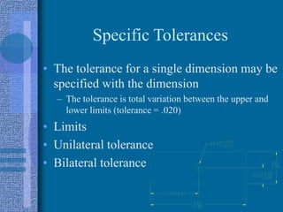
- 8. Specific Tolerances • The tolerance for a single dimension may be specified with the dimension – The tolerance is total variation between the upper and lower limits (tolerance = .020) • Limits • Unilateral tolerance • Bilateral tolerance
- 9. Tolerancing Holes and Shafts • Terms – Basic size: The size to which tolerances are applied – Nominal size: The general size (0.261 { 1/4) – Allowance • The minimum space between two mating parts • Based on the largest shaft and the smallest hole • A negative number indicates that the parts must be forced together – Max. Clearance • The maximum space between mating parts • Based on the smallest shaft and the largest hole
- 10. Tolerancing Holes and Shafts • Types of Fit – Clearance fit • The parts are toleranced such that the largest shaft is smaller than the smallest hole • The allowance is positive and greater than zero – Transition fit • The parts are toleranced such that the allowance is negative and the max. clearance is positive • The parts may be loose or forced together – Interference fit • The max. clearance is always negative • The parts must always be forced together
- 11. Tolerancing Holes and Shafts • Preferred fits: A specified system of fits for holes and shafts for SI units – Hole basis • The minimum hole size equals the basic hole size • Uses the symbol “H” in the tolerance specification – Shaft basis • The maximum shaft size equals the basic shaft size • Uses the symbol “h” in the tolerance specification
- 12. Tolerancing Holes and Shafts • Preferred precision fits: A specified system of fits for holes and shafts for english units – Based on hole basis – Classes of fit specified • RC: Running and sliding – (Allowance >0, Max Clearance >0) • LC: Clearance and locational – (Allowance =0, Max Clearance >0) • LT: Transition locational – (Allowance <0, Max Clearance >0) • LN: Interference locational – (Allowance <0, Max Clearance =0) • FN: Force and shrink – (Allowance <0, Max Clearance <0)
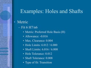
- 13. Examples: Holes and Shafts • Metric – Fit 6 H7/n6 • Metric: Preferred Hole Basis (H) • Allowance: -0.016 • Max. Clearance: 0.004 • Hole Limits: 6.012 / 6.000 • Shaft Limits: 6.016 / 6.008 • Hole Tolerance: 0.012 • Shaft Tolerance: 0.008 • Type of fit: Transition
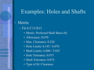
- 14. Examples: Holes and Shafts • Metric – Fit 6 C11/h11 • Metric: Preferred Shaft Basis (h) • Allowance: 0.070 • Max. Clearance: 0.220 • Hole Limits: 6.145 / 6.070 • Shaft Limits: 6.000 / 5.925 • Hole Tolerance: 0.075 • Shaft Tolerance: 0.075 • Type of fit: Clearance
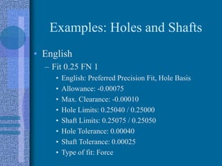
- 15. Examples: Holes and Shafts • English – Fit 0.25 FN 1 • English: Preferred Precision Fit, Hole Basis • Allowance: -0.00075 • Max. Clearance: -0.00010 • Hole Limits: 0.25040 / 0.25000 • Shaft Limits: 0.25075 / 0.25050 • Hole Tolerance: 0.00040 • Shaft Tolerance: 0.00025 • Type of fit: Force
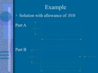
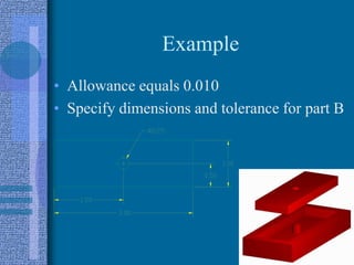
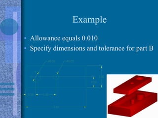
- 16. Example • Part A fits into part B • All dimensions for part A are held !0.010 • Specify the dimensions and tolerance for B with an allowance of 0.010
- 17. Example • Solution with allowance of .010 Part A Part B
- 18. Example • Allowance equals 0.010 • Specify dimensions and tolerance for part B
- 19. Example • Allowance equals 0.010 • Specify dimensions and tolerance for part B


