8051 addressing modes
- 1. MICROCONTROLLERS 8051 Created By: Sachin Bhalavat (Elect. & Comm. Engg.) profspbhalavat@gmail.com
- 3. âĒ The first byte of an instruction is known as the opcode (operation code) because this is the byte that is decoded by the processor - from this code the processor can work out what operation it must perform. âĒ For a one-byte instruction there is only the opcode. âĒ For a two-byte instruction the second byte is the operand. âĒ The operand can be data or an 8-bit address. âĒ For a three-byte instruction the second and third bytes make up the operand. âĒ A two-byte operand is usually a 16-bit address, as we shall see when we look at long addressing
- 4. The five addressing modes are: ïImmediate addressing modes ïRegister addressing modes ïDirect addressing modes ïIndirect addressing modes ïRegister specific addressing mode
- 5. ï Immediate addressing is only use when the data to be read is a constant. ï The data is numeric constant in the operand indicated by a â#â sign ï Useful for getting constants into registers. ï For example, if your program needed to perform some calculations based on the number of weeks in the year, you could use immediate addressing to load the number 52 (34H) into a register and then perform arithmetic operations upon this data. MOV R0, #34H ï The above instruction is an example of immediate addressing. It moves the data 34H into R0. ï The has symbol (#) is used for this purpose (whenever the assembler sees # before a number it knows this is immediate addressing). ï This is a two-byte instruction. ï Data can be 16-bits when dealing with the DPTR register . MOV DPTR, #2500H
- 6. ï Direct access to eight registers (R0-R7). ï There are 4 banks of registers accessible through register addressing. ï Only one bank can be accessed at a time controllable through bit RS0 and RS1 of the PSW. ï Often we need to move data from a register into the accumulator so that we can perform arithmetic operations upon it. For example, we may wish to move the contents of R5 into the accumulator. MOV A, R5 ï This is an example of register addressing. It moves data from R5 (in the currently selected register bank) into the accumulator.
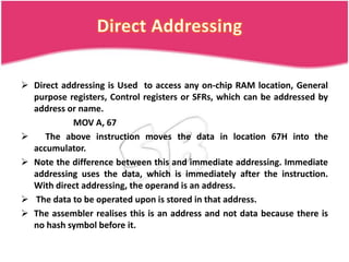
- 7. ï Direct addressing is Used to access any on-chip RAM location, General purpose registers, Control registers or SFRs, which can be addressed by address or name. MOV A, 67 ï The above instruction moves the data in location 67H into the accumulator. ï Note the difference between this and immediate addressing. Immediate addressing uses the data, which is immediately after the instruction. With direct addressing, the operand is an address. ï The data to be operated upon is stored in that address. ï The assembler realises this is an address and not data because there is no hash symbol before it.
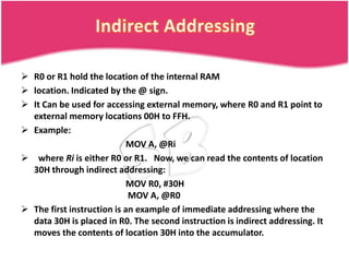
- 8. ï R0 or R1 hold the location of the internal RAM ï location. Indicated by the @ sign. ï It Can be used for accessing external memory, where R0 and R1 point to external memory locations 00H to FFH. ï Example: MOV A, @Ri ï where Ri is either R0 or R1. Now, we can read the contents of location 30H through indirect addressing: MOV R0, #30H MOV A, @R0 ï The first instruction is an example of immediate addressing where the data 30H is placed in R0. The second instruction is indirect addressing. It moves the contents of location 30H into the accumulator.
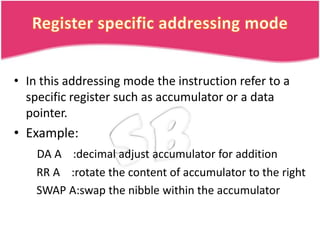
- 9. âĒ In this addressing mode the instruction refer to a specific register such as accumulator or a data pointer. âĒ Example: DA A :decimal adjust accumulator for addition RR A :rotate the content of accumulator to the right SWAP A:swap the nibble within the accumulator


