![(a) CMpitch
vs ╬▒ for varying asym. aileron excitation, Re=8.85e5 (b) CMroll
vs ╬▒ for varying asym. aileron excitation, Re=17.5e5
Fig. 4. Hydrodynamic coef’¼ücients vs ╬▒
Fin. This is done because in the tunnel the ’¼éapping frequency
would also have to be scaled. This gives rise to two problems:
the maximum frequency of the servos is not high enough.
There is not enough space inside the wind tunnel model to
accommodate the ’¼éapping mechanism.
III. PROPULSION
The propulsion system is based on a propulsion technique
called undulating ’¼ün propulsion. This driving mechanism is
found both in BCF (body and/or caudal ’¼ün) and MPF (median
and/or pair ’¼ün) propulsion [1]. A single ’¼ün, steered by 17
Futaba S 3306 servo motors, is placed on each side of the
body to mimic this technique. These two ’¼üns will provide
thrust generation and manoeuvring. By altering independently
the direction of the propulsive wave generated on each ’¼ün,
the robotŌĆÖs manoeuvring possibilities increase: forward and
backward swimming, turning around its vertical axes (yaw)
and hovering. Pitch and roll of the robot is accomplished by
placing two ailerons at the back of the robot. These ailerons
can be steered independently of each other, each by a single
servo motor.
To investigate the capabilities and characteristics of undu-
lating ’¼ün propulsion, a test rig is build, Figure 5(a). The total
’¼ün consists of 17 aluminium rays, each steered independently
by one servo motor. The fabric used to connect these ’¼ün-
segments is cotton because of its easy use. The fabric is
treated with a water-repellent spray. The servo motors that
actuate the push rods attached to the ’¼ün are ’¼üxed in a rack.
This construction rests on a moving frame which enables the
complete test rig to move forward and backward, see Figure
5(b). The movement of the ’¼ün, which is a sinusoidal wave,
is controlled by a test program written in Labview R . The
program enables the operator to change the de’¼éection of the
’¼ün segments, ╬Ė, frequency and non dimensional wave number.
The non-dimensional wave number is given by:
k =
L
╬╗
(1)
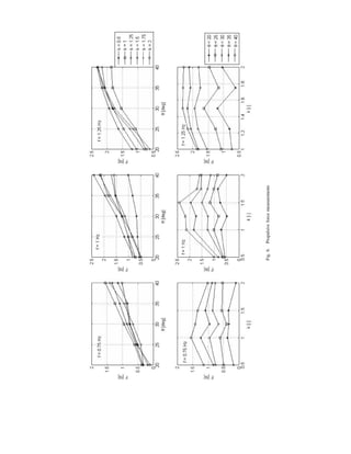
Static thrust experiments are executed varying the three
above mentioned variables. The values of these variables is
summarised in Table I. The length and width of the ’¼ün is
respectively 630 mm by 100 mm. The main goal of the exper-
iment is to con’¼ürm that the mechanical representation of an
undulating ’¼ün is capable of delivering thrust. A second goal is
to get a ’¼ürst insight in the relation between the propulsive force
and de’¼éection, frequency and non-dimensional wave number.
Due to practical limitations, the investigation was limited to
measure static thrust. The propulsion force was measured with
a strain-gauge connected to a picas CA2CF ampli’¼üer. The
ampli’¼üer was connected to a Labview R environment which
registered the measurement values. The signals acquired in the
’¼ürst 20 cycles were ignored due to instabilities. The forces
presented in Figure 6 are averaged values over 30 cycles.
The following trends can be seen: an increase in de’¼éection
(and with this the amplitude) and/or frequency will result
in an increase of the propulsive force. The combination of
frequency and amplitude is limited by the maximum angular
velocity of the actuators. The in’¼éuence of the non-dimensional
wave number was different than expected [2]. In undulating
propulsion the wave velocity is one of the main parameters.
It is given by:
vw = ╬╗f =
L f
k
(2)
A higher wave velocity will result a higher trust. According
to Equation 2, a lower wave number will result in a higher
wave velocity and a higher trust. As can be seen in the
measurements, this trend is not very clear. A non dimensional
wave number of 0.5, which is an oscillating mode, gives very
poor results. This is due to the loss of energy due to large
vibrations. Because of this, the frame could not hold its parallel](https://image.slidesharecdn.com/02f6375b-7fbd-4262-b01a-0565a3a89c01-160302153411/85/A-highly-versatile-autonomous-underwater-vehicle-3-320.jpg)
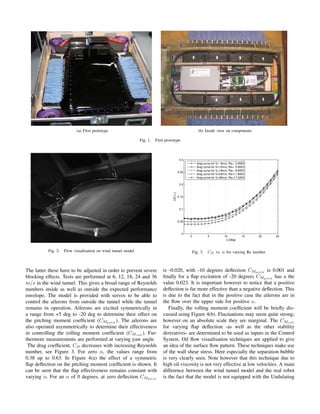
![(a) Detailed view on the ’¼ün testrig (b) Fin propulsion test facility
Fig. 5. Fin propulsion tests
TABLE I
TEST VARIABLE RANGE
Variable Value range
╬Ė [20: 5: 40]
k 0.511.51.752
f 0.7511.25
alignment with the swimming direction. To make a better
analysis a more detailed investigation is necessary.
Together with investigating the in’¼éuence of different vari-
ables, a ’¼ürst prototype of a ’¼ün, as will be used in the ’¼ürst
prototype of the robot has been developed.
IV. CONTROL
At the heart of the Galatea robot is a pair of ET-Base
AVR ATMega 128 Microcontrollers. The main task of these
microcontrollers is to translate the pilot commands into control
signals for the servo motors that are actuating the ’¼üns and the
control surfaces. For this task, use is made of the two RS-232
communication ports that are present on each microcontroller.
Additionally, the microcontrollers have a number of ADCŌĆÖs
that can be used to read out on-board analog sensors, such
as temperature or humidity sensors. The software for the
microcontrollers was implemented in C.
At present, Galatea is equipped with a manual control sys-
tem, that allows the pilot to directly control the robot. The pilot
can change the frequency of the ’¼üns, both symmetrically, to
vary the thrust, or asymmetrically to induce a moment around
the vertical axis (yaw). The setting of the control surfaces
can also be changed directly, either symmetrically to induce
a moment around the lateral axis (pitch) or asymmetrically
to induce a moment around the longitudinal axis (roll). The
pilot can apply these changes using a virtual instrument panel
created in National InstrumentŌĆÖs LabView R , see Figure 7.
Communications between the virtual instrument panel and
Galatea run through both a tether and wireless modem during
Fig. 7. LabView R instrument panel
the development phase. For this purpose, one of the RS-232
interfaces on the microcontrollers is used in combination with
a serial port on the computer. The possibilities for wireless
communications are being investigated in cooperation with
Wireless Fiber Systems Ltd., a producer of underwater radio
modems.
GalateaŌĆÖs control system is planned to be improved to
become fully autonomous. An important instrument to achieve
this will be the MTi, produced by Xsens Technologies B.V.
This miniature Attitude and Heading Reference System will
provide drift-free attitude determination data that will allow
to implement a feedback-based control system. This would
allow Galatea to maintain a certain heading or to perform a
coordinated turn. Using a pressure sensor, Galatea would also
be able to maintain a certain depth or to change itŌĆÖs depth in a
controlled fashion. Full autonomy could be achieved with the
addition of a position determination system.
Adding these extra functionalities to the control system
would signi’¼ücantly increase the computational power required.
Therefore, options for a more powerful controller are currently](https://image.slidesharecdn.com/02f6375b-7fbd-4262-b01a-0565a3a89c01-160302153411/85/A-highly-versatile-autonomous-underwater-vehicle-4-320.jpg)
![being investigated. One of the options under consideration is
a single-board computer (SBC).
V. SENSORS
In the very near future the prototype will be equipped
with a simple single sensor, e.g. a hydrophone for performing
ambient noise level measurements in harbours (interest of the
Netherlands Navy) or a chemical sensor for pollution mea-
surements in inland waters (interest of the Dutch Ministry of
Transport, Public Works and Water Management). Ultimately,
our goal is to develop a harbour protection system consisting
of a swarm of communicating Galatea AUVs.
VI. FUTURE DEVELOPMENT
With the ’¼ürst prototype ready, multiple tests will be con-
ducted. These tests will include the programming and analysis
of various swimming and turning modes. In a further stage,
the robot will be programmed in such a way that it can do
autonomous missions in closed water environment. A third
goal is to improve the transmission section of the ’¼ün, which
should be made more reliable and robust. A new design of
the robot will be focussed on making the robot modular. This
means that several independent modules will be developed that
can be put together to one robot depending on the mission.
This way, the maintainability and ’¼éexibility of the robot will
increase.
As there is still a lot unknown about the working of
undulating ’¼ün propulsion and the conversion to a mechanical
level, three graduation projects at the Faculty of Aerospace
Engineering at the TU Delft are now set up. A ’¼ürst project
concerns the development of a Particle Image Velocimetry
(PIV) measurement set-up that will be used to visualise the
’¼éow around a working ’¼ün. This will give an insight in the
dynamics of the surrounding ’¼éow. Preliminary tests are done
with a working ’¼ün in a small pool to get a ’¼ürst impression of
the placement of the lasers and cameras. A second graduation
project will aim to distinguish the most important parame-
ters and variables that characterise undulating ’¼ün propulsion.
With this knowledge, a mechanical propulsion system using
undulating ’¼ün propulsion will be developed and tested. This
research will be done in close cooperation with the Chair
of Experimental Zoology at Wageningen University. This
improved ’¼ün will be used in a next prototype of the Galatea
robot. A third graduation student will write a CFD code to
visualise the ’¼éow around a working ’¼ün. As experimental
testing is very time consuming, this code will help to get
more rapidly, accurate ’¼éow data for different ’¼ün movements.
This CFD code will be written in close cooperation with the
students of the ’¼ürst two projects, aiming at a comparison
between experimental and computational results.
VII. CONCLUSIONS
A ’¼ürst prototype of a bio-mimetic AUV with undulating
’¼ün propulsion has been build. Research has been done into
its propulsion system and its hydrodynamic properties. Three
Master Thesis projects have been de’¼üned around Galatea,
covering the topics PIV, CFD and the propulsion itself. Cur-
rently the team is familiarising itself with the robotŌĆÖs controls
and thinking about possible improvements. The next phase
is to redesign the robot using our gained experience with an
emphasis on a modular layout. After this phase it is time to
aim at increasing GalateaŌĆÖs level of autonomy.
ACKNOWLEDGEMENT
The Galatea team would like to thank the people at PMB
(Metallurgy Workshop), DASML (Delft Aerospace Structures
and Materials Laboratory), 3Me Towing tank, Low-speed wind
tunnel laboratories and Chair of Experimental Zoology of the
WUR for sharing their experience, knowledge and enthusiasm.
REFERENCES
[1] M. Sfakiotakis, D.M. Lane and J.B.C. Davies, Review of Fish Swimming
Modes for Aquatic Locomotion, IEEE Journal of Oceanic Engineering,
Vol. 24, no.2, April 1999.
[2] C. Zhang, L. Zhuang and X. Lu, Analysis of hydrodynamics for two-
dimensional ’¼éow around waving plates, Journal of Hydrodynamics,
Ser. B, Vol. 19, no.1, 2007.](https://image.slidesharecdn.com/02f6375b-7fbd-4262-b01a-0565a3a89c01-160302153411/85/A-highly-versatile-autonomous-underwater-vehicle-6-320.jpg)
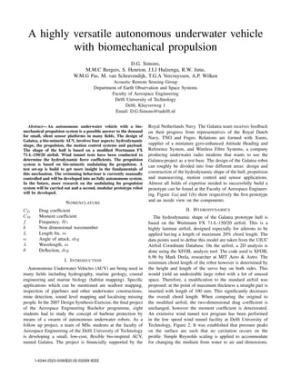
A highly versatile autonomous underwater vehicle
- 1. A highly versatile autonomous underwater vehicle with biomechanical propulsion D.G. Simons, M.M.C Bergers, S. Henrion, J.I.J Hulzenga, R.W. Jutte, W.M.G Pas, M. van Schravendijk, T.G.A Vercruyssen, A.P. Wilken Acoustic Remote Sensing Group Department of Earth Observation and Space Systems Faculty of Aerospace Engineering Delft University of Technology Delft, Kluyverweg 1 Email: D.G.Simons@tudelft.nl AbstractŌĆö An autonomous underwater vehicle with a bio- mechanical propulsion system is a possible answer to the demand for small, silent sensor platforms in many ’¼üelds. The design of Galatea, a bio-mimetic AUV, involves four aspects: hydrodynamic shape, the propulsion, the motion control systems and payload. The shape of the hull is based on a modi’¼üed Wortmann FX 71-L-150/20 airfoil. Wind tunnel tests have been conducted to determine the hydrodynamic force coef’¼ücients. The propulsion system is based on bio-mimetic undulating ’¼ün propulsion. A test set-up is build to get more insight in the fundamentals of this mechanism. The swimming behaviour is currently manually controlled and will be developed into an fully autonomous system. In the future, more research on the undulating ’¼ün propulsion system will be carried out and a second, modular prototype robot will be developed. NOMENCLATURE CD Drag coef’¼ücient CM Moment coef’¼ücient f Frequency, Hz k Non dimensional wavenumber L Length ’¼ün, m ╬▒ Angle of attack, deg ╬╗ Wavelength, m ╬Ė De’¼éection, deg I. INTRODUCTION Autonomous Underwater Vehicles (AUV) are being used in many ’¼üelds including hydrography, marine geology, coastal engineering and marine biology (habitat mapping). Speci’¼üc applications which can be mentioned are sea’¼éoor mapping, inspection of pipelines and other underwater constructions, mine detection, sound level mapping and localising missing people. In the 2007 Design Synthesis Exercise, the ’¼ünal project of the Aerospace Engineering Bachelor programme, eight students had to study the concept of harbour protection by means of a swarm of autonomous underwater robots. As a follow up project, a team of MSc students at the faculty of Aerospace Engineering of the Delft University of Technology is developing a small, low-cost, ’¼éexible bio-inspired AUV, named Galatea. The project is ’¼ünancially supported by the Royal Netherlands Navy. The Galatea team receives feedback on their progress from representatives of the Royal Dutch Navy, TNO and Fugro. Relations are formed with Xsens, supplier of a miniature gyro-enhanced Attitude Heading and Reference System, and Wireless Fibre Systems, a company producing underwater radio modems that wants to use the Galatea-project as a test base. The design of the Galatea robot can roughly be divided into four different areas: design and construction of the hydrodynamic shape of the hull, propulsion and manoeuvring, motion control and sensor applications. Almost all ’¼üelds of expertise needed to successfully build a prototype can be found at the Faculty of Aerospace Engineer- ing. Figure 1(a) and 1(b) show respectively the ’¼ürst prototype and an inside view on the components. II. HYDRODYNAMICS The hydrodynamic shape of the Galatea prototype hull is based on the Wortmann FX 71-L-150/20 airfoil. This is a highly laminar airfoil, designed especially for ailerons to be applied having a length of maximum 20% chord length. The data points used to de’¼üne this model are taken from the UIUC Airfoil Coordinate Database. On the airfoil, a 2D analysis is done using the XFOIL analysis tool. The code used is XFOIL 6.96 by Mark Drela, researcher at MIT Aero & Astro. The minimum chord length of the robot however is determined by the height and length of the servo bay on both sides. This would yield an undesirable large robot with a lot of unused space. Therefore, a modi’¼ücation to the standard airfoil was proposed: at the point of maximum thickness a straight part is inserted with length of 100 mm. This signi’¼ücantly decreases the overall chord length. When comparing the original to the modi’¼üed airfoil, the two-dimensional drag coef’¼ücient is unchanged, however the moment coef’¼ücient is deteriorated. An extensive wind tunnel test program has been performed in the low speed wind tunnel facility at Delft University of Technology, Figure 2. It was established that pressure peaks on the surface are such that no cavitation occurs on the pro’¼üle. Simple Reynolds scaling is applied to accommodate for changing the medium from water to air and dimensions. 1-4244-2523-5/09/$20.00 ┬®2009 IEEE
- 2. (a) First prototype (b) Inside view on components Fig. 1. First prototype Fig. 2. Flow visualisation on wind tunnel model The latter these have to be adjusted in order to prevent severe blocking effects. Tests are performed at 6, 12, 18, 24 and 36 m/s in the wind tunnel. This gives a broad range of Reynolds numbers inside as well as outside the expected performance envelope. The model is provided with servos to be able to control the ailerons from outside the tunnel while the tunnel remains in operation. Ailerons are excited symmetrically in a range from +5 deg to -20 deg to determine their effect on the pitching moment coef’¼ücient (CMpitch ). The ailerons are also operated asymmetrically to determine their effectiveness in controlling the rolling moment coef’¼ücient (CMroll ). Fur- thermore measurements are performed at varying yaw angle. The drag coef’¼ücient, CD decreases with increasing Reynolds number, see Figure 3. For zero ╬▒, the values range from 0.38 up to 0.63. In Figure 4(a) the effect of a symmetric ’¼éap de’¼éection on the pitching moment coef’¼ücient is shown. It can be seen that the ’¼éap effectiveness remains constant with varying ╬▒. For an ╬▒ of 0 degrees, at zero de’¼éection CMpitch Fig. 3. CD vs. ╬▒ for varying Re number is -0.020, with -10 degrees de’¼éection CMpitch is 0.001 and ’¼ünally for a ’¼éap excitation of -20 degrees CMpitch has a the value 0.023. It is important however to notice that a positive de’¼éection is far more effective than a negative de’¼éection. This is due to the fact that in the positive case the ailerons are in the ’¼éow over the upper side for positive ╬▒. Finally, the rolling moment coef’¼ücient will be brie’¼éy dis- cussed using Figure 4(b). Fluctuations may seem quite strong; however on an absolute scale they are marginal. The CMroll for varying ’¼éap de’¼éection -as well as the other stability derivatives- are determined to be used as inputs in the Control System. Oil ’¼éow visualisation techniques are applied to give an idea of the surface ’¼éow pattern. These techniques make use of the wall shear stress. Here especially the separation bubble is very clearly seen. Note however that this technique due to high oil viscosity is not very effective at low velocities. A main difference between the wind tunnel model and the real robot is the fact that the model is not equipped with the Undulating
- 3. (a) CMpitch vs ╬▒ for varying asym. aileron excitation, Re=8.85e5 (b) CMroll vs ╬▒ for varying asym. aileron excitation, Re=17.5e5 Fig. 4. Hydrodynamic coef’¼ücients vs ╬▒ Fin. This is done because in the tunnel the ’¼éapping frequency would also have to be scaled. This gives rise to two problems: the maximum frequency of the servos is not high enough. There is not enough space inside the wind tunnel model to accommodate the ’¼éapping mechanism. III. PROPULSION The propulsion system is based on a propulsion technique called undulating ’¼ün propulsion. This driving mechanism is found both in BCF (body and/or caudal ’¼ün) and MPF (median and/or pair ’¼ün) propulsion [1]. A single ’¼ün, steered by 17 Futaba S 3306 servo motors, is placed on each side of the body to mimic this technique. These two ’¼üns will provide thrust generation and manoeuvring. By altering independently the direction of the propulsive wave generated on each ’¼ün, the robotŌĆÖs manoeuvring possibilities increase: forward and backward swimming, turning around its vertical axes (yaw) and hovering. Pitch and roll of the robot is accomplished by placing two ailerons at the back of the robot. These ailerons can be steered independently of each other, each by a single servo motor. To investigate the capabilities and characteristics of undu- lating ’¼ün propulsion, a test rig is build, Figure 5(a). The total ’¼ün consists of 17 aluminium rays, each steered independently by one servo motor. The fabric used to connect these ’¼ün- segments is cotton because of its easy use. The fabric is treated with a water-repellent spray. The servo motors that actuate the push rods attached to the ’¼ün are ’¼üxed in a rack. This construction rests on a moving frame which enables the complete test rig to move forward and backward, see Figure 5(b). The movement of the ’¼ün, which is a sinusoidal wave, is controlled by a test program written in Labview R . The program enables the operator to change the de’¼éection of the ’¼ün segments, ╬Ė, frequency and non dimensional wave number. The non-dimensional wave number is given by: k = L ╬╗ (1) Static thrust experiments are executed varying the three above mentioned variables. The values of these variables is summarised in Table I. The length and width of the ’¼ün is respectively 630 mm by 100 mm. The main goal of the exper- iment is to con’¼ürm that the mechanical representation of an undulating ’¼ün is capable of delivering thrust. A second goal is to get a ’¼ürst insight in the relation between the propulsive force and de’¼éection, frequency and non-dimensional wave number. Due to practical limitations, the investigation was limited to measure static thrust. The propulsion force was measured with a strain-gauge connected to a picas CA2CF ampli’¼üer. The ampli’¼üer was connected to a Labview R environment which registered the measurement values. The signals acquired in the ’¼ürst 20 cycles were ignored due to instabilities. The forces presented in Figure 6 are averaged values over 30 cycles. The following trends can be seen: an increase in de’¼éection (and with this the amplitude) and/or frequency will result in an increase of the propulsive force. The combination of frequency and amplitude is limited by the maximum angular velocity of the actuators. The in’¼éuence of the non-dimensional wave number was different than expected [2]. In undulating propulsion the wave velocity is one of the main parameters. It is given by: vw = ╬╗f = L f k (2) A higher wave velocity will result a higher trust. According to Equation 2, a lower wave number will result in a higher wave velocity and a higher trust. As can be seen in the measurements, this trend is not very clear. A non dimensional wave number of 0.5, which is an oscillating mode, gives very poor results. This is due to the loss of energy due to large vibrations. Because of this, the frame could not hold its parallel
- 4. (a) Detailed view on the ’¼ün testrig (b) Fin propulsion test facility Fig. 5. Fin propulsion tests TABLE I TEST VARIABLE RANGE Variable Value range ╬Ė [20: 5: 40] k 0.511.51.752 f 0.7511.25 alignment with the swimming direction. To make a better analysis a more detailed investigation is necessary. Together with investigating the in’¼éuence of different vari- ables, a ’¼ürst prototype of a ’¼ün, as will be used in the ’¼ürst prototype of the robot has been developed. IV. CONTROL At the heart of the Galatea robot is a pair of ET-Base AVR ATMega 128 Microcontrollers. The main task of these microcontrollers is to translate the pilot commands into control signals for the servo motors that are actuating the ’¼üns and the control surfaces. For this task, use is made of the two RS-232 communication ports that are present on each microcontroller. Additionally, the microcontrollers have a number of ADCŌĆÖs that can be used to read out on-board analog sensors, such as temperature or humidity sensors. The software for the microcontrollers was implemented in C. At present, Galatea is equipped with a manual control sys- tem, that allows the pilot to directly control the robot. The pilot can change the frequency of the ’¼üns, both symmetrically, to vary the thrust, or asymmetrically to induce a moment around the vertical axis (yaw). The setting of the control surfaces can also be changed directly, either symmetrically to induce a moment around the lateral axis (pitch) or asymmetrically to induce a moment around the longitudinal axis (roll). The pilot can apply these changes using a virtual instrument panel created in National InstrumentŌĆÖs LabView R , see Figure 7. Communications between the virtual instrument panel and Galatea run through both a tether and wireless modem during Fig. 7. LabView R instrument panel the development phase. For this purpose, one of the RS-232 interfaces on the microcontrollers is used in combination with a serial port on the computer. The possibilities for wireless communications are being investigated in cooperation with Wireless Fiber Systems Ltd., a producer of underwater radio modems. GalateaŌĆÖs control system is planned to be improved to become fully autonomous. An important instrument to achieve this will be the MTi, produced by Xsens Technologies B.V. This miniature Attitude and Heading Reference System will provide drift-free attitude determination data that will allow to implement a feedback-based control system. This would allow Galatea to maintain a certain heading or to perform a coordinated turn. Using a pressure sensor, Galatea would also be able to maintain a certain depth or to change itŌĆÖs depth in a controlled fashion. Full autonomy could be achieved with the addition of a position determination system. Adding these extra functionalities to the control system would signi’¼ücantly increase the computational power required. Therefore, options for a more powerful controller are currently
- 6. being investigated. One of the options under consideration is a single-board computer (SBC). V. SENSORS In the very near future the prototype will be equipped with a simple single sensor, e.g. a hydrophone for performing ambient noise level measurements in harbours (interest of the Netherlands Navy) or a chemical sensor for pollution mea- surements in inland waters (interest of the Dutch Ministry of Transport, Public Works and Water Management). Ultimately, our goal is to develop a harbour protection system consisting of a swarm of communicating Galatea AUVs. VI. FUTURE DEVELOPMENT With the ’¼ürst prototype ready, multiple tests will be con- ducted. These tests will include the programming and analysis of various swimming and turning modes. In a further stage, the robot will be programmed in such a way that it can do autonomous missions in closed water environment. A third goal is to improve the transmission section of the ’¼ün, which should be made more reliable and robust. A new design of the robot will be focussed on making the robot modular. This means that several independent modules will be developed that can be put together to one robot depending on the mission. This way, the maintainability and ’¼éexibility of the robot will increase. As there is still a lot unknown about the working of undulating ’¼ün propulsion and the conversion to a mechanical level, three graduation projects at the Faculty of Aerospace Engineering at the TU Delft are now set up. A ’¼ürst project concerns the development of a Particle Image Velocimetry (PIV) measurement set-up that will be used to visualise the ’¼éow around a working ’¼ün. This will give an insight in the dynamics of the surrounding ’¼éow. Preliminary tests are done with a working ’¼ün in a small pool to get a ’¼ürst impression of the placement of the lasers and cameras. A second graduation project will aim to distinguish the most important parame- ters and variables that characterise undulating ’¼ün propulsion. With this knowledge, a mechanical propulsion system using undulating ’¼ün propulsion will be developed and tested. This research will be done in close cooperation with the Chair of Experimental Zoology at Wageningen University. This improved ’¼ün will be used in a next prototype of the Galatea robot. A third graduation student will write a CFD code to visualise the ’¼éow around a working ’¼ün. As experimental testing is very time consuming, this code will help to get more rapidly, accurate ’¼éow data for different ’¼ün movements. This CFD code will be written in close cooperation with the students of the ’¼ürst two projects, aiming at a comparison between experimental and computational results. VII. CONCLUSIONS A ’¼ürst prototype of a bio-mimetic AUV with undulating ’¼ün propulsion has been build. Research has been done into its propulsion system and its hydrodynamic properties. Three Master Thesis projects have been de’¼üned around Galatea, covering the topics PIV, CFD and the propulsion itself. Cur- rently the team is familiarising itself with the robotŌĆÖs controls and thinking about possible improvements. The next phase is to redesign the robot using our gained experience with an emphasis on a modular layout. After this phase it is time to aim at increasing GalateaŌĆÖs level of autonomy. ACKNOWLEDGEMENT The Galatea team would like to thank the people at PMB (Metallurgy Workshop), DASML (Delft Aerospace Structures and Materials Laboratory), 3Me Towing tank, Low-speed wind tunnel laboratories and Chair of Experimental Zoology of the WUR for sharing their experience, knowledge and enthusiasm. REFERENCES [1] M. Sfakiotakis, D.M. Lane and J.B.C. Davies, Review of Fish Swimming Modes for Aquatic Locomotion, IEEE Journal of Oceanic Engineering, Vol. 24, no.2, April 1999. [2] C. Zhang, L. Zhuang and X. Lu, Analysis of hydrodynamics for two- dimensional ’¼éow around waving plates, Journal of Hydrodynamics, Ser. B, Vol. 19, no.1, 2007.