際際滷

際際滷Share a Scribd company logo
Aees notes wiring
The ignition switch supplies electrical power for the wiper motor. Current passes
through the wiper control switch and then to the wiper motor. A speed control module may
vary the voltage that reaches the motor on some models. Other types use different windings in
the motor to control speed.
Within the wiper-motor is another switch, with voltage that bypasses the off-switch.
The motor times this device with the full down position. Many use a cam to open the circuit
when the motor achieves wiper parking. Turn off the wiper switch and current continues to
flow through the park-switch, until the wipers are fully down..
Importance of colour coding in automobile wiring: (4 Mark)
Automobile wiring is complicated because of number of lamps and accessories for this
color coding is necessary due to which wiring can easily identify for specific lamp and
accessories and also it is easier during maintenance.
OR
With the help of color codes of electrical wires, they can be easily and safely identified.
There are some safety measurements that are to be followed while dealing with electrical wiring
and the color codes of wires will help in implementing those safety measurements. colour coding
is provided with the automobile wiring harnesses for fault diagnosis and repair works.
The colour coding will identifies the part of circuit formed by this cable
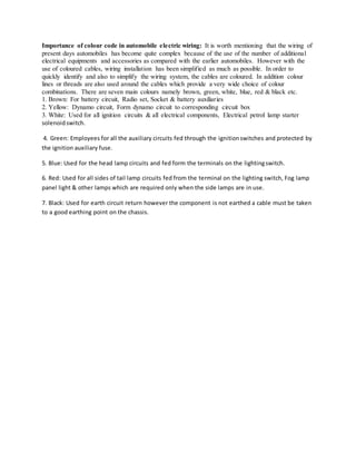
Importance of colour code in automobile electric wiring: It is worth mentioning that the wiring of
present days automobiles has become quite complex because of the use of the number of additional
electrical equipments and accessories as compared with the earlier automobiles. However with the
use of coloured cables, wiring installation has been simplified as much as possible. In order to
quickly identify and also to simplify the wiring system, the cables are coloured. In addition colour
lines or threads are also used around the cables which provide a very wide choice of colour
combinations. There are seven main colours namely brown, green, white, blue, red & black etc.
1. Brown: For battery circuit, Radio set, Socket & battery auxiliaries
2. Yellow: Dynamo circuit, Form dynamo circuit to corresponding circuit box
3. White: Used for all ignition circuits & all electrical components, Electrical petrol lamp starter
solenoidswitch.
4. Green: Employees for all the auxiliary circuits fed through the ignitionswitches and protected by
the ignition auxiliary fuse.
5. Blue: Used for the head lamp circuits and fed form the terminals on the lightingswitch.
6. Red: Used for all sides of tail lamp circuits fed from the terminal on the lighting switch, Fog lamp
panel light & other lamps which are required only when the side lamps are in use.
7. Black: Used for earth circuit return however the component is not earthed a cable must be taken
to a good earthing point on the chassis.
Turn indicator The direction indicators permit the driver to signal his intention to make a right or a
left turn. Figure shows the circuit diagram of this type of direction indicator. When the signal lever is
moved one or the other way, the circuit is completed between the battery and the proper indicating
lights on the front and the rear of the vehicle as well as on the dash board. The circuit is completed
through a flasher unit which is a device that closes and opens the circuit about 70 to 80 times per
minute. This sends a flashing signal which is more noticeable than a steady light. The flashing action
takes place because of the heating of a thermostatic blade in the flasher unit. When the blade is
heated due to current flowing through the winding of the flasher, it wraps thereby opening a pair of
contacts. It in turn opens the circuit. After this the blade cools and straightens to close the circuit.
Aees notes wiring
Aees notes wiring
Aees notes wiring
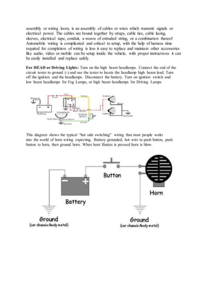
A cable harness, also known as a wire harness, cable assembly, wiring
assembly or wiring loom, is an assembly of cables or wires which transmit signals or
electrical power. The cables are bound together by straps, cable ties, cable lacing,
sleeves, electrical tape, conduit, a weave of extruded string, or a combination thereof
Automobile wiring is complicated and critical to setup, with the help of harness time
required for completion of wiring is less it easy to replace and maintain other accessories
like audio, video or mobile can be setup inside the vehicle, with proper instructions it can
be easily installed and replace safely.
For HEAD or Driving Lights: Turn on the high beam headlamps. Connect the end of the
circuit tester to ground (-) and use the tester to locate the headlamp high beam lead. Turn
off the ignition and the headlamps. Disconnect the battery. Turn on ignition switch and
low beam headlamps for Fog Lamps, or high beam headlamps for Driving Lamps
This diagram shows the typical hot side switching wiring that most people waltz
into the world of horn wiring expecting. Battery grounded, hot wire to push button, push
button to horn, then ground horn. When horn Butten is pressed horn is blow.
When breaks are applied in a vehicle, break switches are put in close or ON position.
the break lights get supply from battery and blow out.
The turn indicator is a gyroscopic instrument that works on the principle of
precession. The gyro is mounted in a gimbal. The gyro's rotational axis is in-line with the
lateral (pitch) axis of the aircraft, while the gimbal has limited freedom around the
longitudinal (roll) axis of the aircraft. OR
It is a device consisting of a wheel or disc mounted so that it can spin
rapidly about an axis which is itself free to alter in direction. The orientation of the axis is not
affected by tilting of the mounting, so gyroscopes can be used to provide stability
or maintain a reference direction in navigation systems, automatic pilots, and stabilizers.
The ignition switch supplies electrical power for the wiper motor. Current passes
through the wiper control switch and then to the wiper motor. A speed control module may
vary the voltage that reaches the motor on some models. Other types use different windings
in the motor to control speed.
Within the wiper-motor is another switch, with voltage that bypasses the off-switch.
The motor times this device with the full down position. Many use a cam to open the circuit
when the motor achieves wiper parking. Turn off the wiper switch and current continues to
flow through the park-switch, until the wipers are fully down.
Reason speed is controlled in wiper:-
The ignition switch supplies electrical power for the wiper motor. Current passes
through the wiper control switch and then to the wiper motor. A speed control module may
vary the voltage that reaches the motor on some models. Other types use different windings in
the motor to control speed.
Within the wiper-motor is another switch, with voltage that bypasses the off-switch.
The motor times this device with the full down position. Many use a cam to open the circuit
when the motor achieves wiper parking. Turn off the wiper switch and current continues to
flow through the park-switch, until the wipers are fully down.

More Related Content

Aees notes wiring

  • 2. The ignition switch supplies electrical power for the wiper motor. Current passes through the wiper control switch and then to the wiper motor. A speed control module may vary the voltage that reaches the motor on some models. Other types use different windings in the motor to control speed. Within the wiper-motor is another switch, with voltage that bypasses the off-switch. The motor times this device with the full down position. Many use a cam to open the circuit when the motor achieves wiper parking. Turn off the wiper switch and current continues to flow through the park-switch, until the wipers are fully down..
  • 3. Importance of colour coding in automobile wiring: (4 Mark) Automobile wiring is complicated because of number of lamps and accessories for this color coding is necessary due to which wiring can easily identify for specific lamp and accessories and also it is easier during maintenance. OR With the help of color codes of electrical wires, they can be easily and safely identified. There are some safety measurements that are to be followed while dealing with electrical wiring and the color codes of wires will help in implementing those safety measurements. colour coding is provided with the automobile wiring harnesses for fault diagnosis and repair works. The colour coding will identifies the part of circuit formed by this cable
  • 4. Importance of colour code in automobile electric wiring: It is worth mentioning that the wiring of present days automobiles has become quite complex because of the use of the number of additional electrical equipments and accessories as compared with the earlier automobiles. However with the use of coloured cables, wiring installation has been simplified as much as possible. In order to quickly identify and also to simplify the wiring system, the cables are coloured. In addition colour lines or threads are also used around the cables which provide a very wide choice of colour combinations. There are seven main colours namely brown, green, white, blue, red & black etc. 1. Brown: For battery circuit, Radio set, Socket & battery auxiliaries 2. Yellow: Dynamo circuit, Form dynamo circuit to corresponding circuit box 3. White: Used for all ignition circuits & all electrical components, Electrical petrol lamp starter solenoidswitch. 4. Green: Employees for all the auxiliary circuits fed through the ignitionswitches and protected by the ignition auxiliary fuse. 5. Blue: Used for the head lamp circuits and fed form the terminals on the lightingswitch. 6. Red: Used for all sides of tail lamp circuits fed from the terminal on the lighting switch, Fog lamp panel light & other lamps which are required only when the side lamps are in use. 7. Black: Used for earth circuit return however the component is not earthed a cable must be taken to a good earthing point on the chassis.
  • 5. Turn indicator The direction indicators permit the driver to signal his intention to make a right or a left turn. Figure shows the circuit diagram of this type of direction indicator. When the signal lever is moved one or the other way, the circuit is completed between the battery and the proper indicating lights on the front and the rear of the vehicle as well as on the dash board. The circuit is completed through a flasher unit which is a device that closes and opens the circuit about 70 to 80 times per minute. This sends a flashing signal which is more noticeable than a steady light. The flashing action takes place because of the heating of a thermostatic blade in the flasher unit. When the blade is heated due to current flowing through the winding of the flasher, it wraps thereby opening a pair of contacts. It in turn opens the circuit. After this the blade cools and straightens to close the circuit.
  • 9. A cable harness, also known as a wire harness, cable assembly, wiring
  • 10. assembly or wiring loom, is an assembly of cables or wires which transmit signals or electrical power. The cables are bound together by straps, cable ties, cable lacing, sleeves, electrical tape, conduit, a weave of extruded string, or a combination thereof Automobile wiring is complicated and critical to setup, with the help of harness time required for completion of wiring is less it easy to replace and maintain other accessories like audio, video or mobile can be setup inside the vehicle, with proper instructions it can be easily installed and replace safely. For HEAD or Driving Lights: Turn on the high beam headlamps. Connect the end of the circuit tester to ground (-) and use the tester to locate the headlamp high beam lead. Turn off the ignition and the headlamps. Disconnect the battery. Turn on ignition switch and low beam headlamps for Fog Lamps, or high beam headlamps for Driving Lamps This diagram shows the typical hot side switching wiring that most people waltz into the world of horn wiring expecting. Battery grounded, hot wire to push button, push button to horn, then ground horn. When horn Butten is pressed horn is blow.
  • 11. When breaks are applied in a vehicle, break switches are put in close or ON position. the break lights get supply from battery and blow out. The turn indicator is a gyroscopic instrument that works on the principle of precession. The gyro is mounted in a gimbal. The gyro's rotational axis is in-line with the lateral (pitch) axis of the aircraft, while the gimbal has limited freedom around the longitudinal (roll) axis of the aircraft. OR It is a device consisting of a wheel or disc mounted so that it can spin rapidly about an axis which is itself free to alter in direction. The orientation of the axis is not affected by tilting of the mounting, so gyroscopes can be used to provide stability or maintain a reference direction in navigation systems, automatic pilots, and stabilizers. The ignition switch supplies electrical power for the wiper motor. Current passes through the wiper control switch and then to the wiper motor. A speed control module may vary the voltage that reaches the motor on some models. Other types use different windings in the motor to control speed. Within the wiper-motor is another switch, with voltage that bypasses the off-switch. The motor times this device with the full down position. Many use a cam to open the circuit when the motor achieves wiper parking. Turn off the wiper switch and current continues to flow through the park-switch, until the wipers are fully down.
  • 12. Reason speed is controlled in wiper:- The ignition switch supplies electrical power for the wiper motor. Current passes through the wiper control switch and then to the wiper motor. A speed control module may vary the voltage that reaches the motor on some models. Other types use different windings in the motor to control speed. Within the wiper-motor is another switch, with voltage that bypasses the off-switch. The motor times this device with the full down position. Many use a cam to open the circuit when the motor achieves wiper parking. Turn off the wiper switch and current continues to flow through the park-switch, until the wipers are fully down.