Aiaa 2012 Presentation
0 likes393 views

This study evaluated the effects of supporting brackets and mesh refinement on the aerodynamic coefficients of a trapezoidal wing configuration. The coarse mesh showed premature stall compared to experimental data. Surface mesh refinement improved results, but volumetric refinement unexpectedly decreased stall angle and maximum lift. Different turbulence models produced varying flow patterns. Further systematic mesh refinement studies are needed.


Aiaa 2012 Presentation
- 1. INFLUENCE OF HIGH-LIFT SUPPORTING SYSTEMS ON THE TRAPEZOIDAL WING AERODYNAMIC COEFFICIENTS Alexandre P. Antunes Embraer, SÃĢo JosÃĐ dos Campos, Brazil Ricardo Galdino da Silva Embraer, SÃĢo JosÃĐ dos Campos, Brazil JoÃĢo Luiz F. Azevedo Instituto de AeronÃĄutica e Espaço, SÃĢo JosÃĐ dos Campos, Brazil 30th AIAA Applied Aerodynamic Conference New Orleans, Louisiana â 25-28 June 2012
- 2. Outline Objectives Theoretical and Numerical Formulations High-Lift Configuration Mesh Generation Results Conclusions
- 3. Outline Objectives Theoretical and Numerical Formulations High-Lift Configuration Mesh Generation Results Conclusions
- 4. Objectives The main objectives of the present work are: Build upon previous work but now considering the effects of the supporting brackets over the aerodynamic coefficients for the trapezoidal wing. Evaluate the effects of a surface and a volumetric mesh refinement over the aerodynamic coefficients.
- 5. Outline Objectives Theoretical and Numerical Formulations High-Lift Configuration Mesh Generation Results Conclusions
- 6. Outline Objectives Theoretical and Numerical Formulations High-Lift Configuration Mesh Generation Results Conclusions
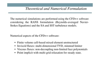
- 7. Theoretical and Numerical Formulation The numerical simulations are performed using the CFD++ software considering the RANS formulation (Reynolds-averaged Navier- Stokes Equations) and the SA and SST turbulence models. Numerical aspects of the CFD++ software: âĒ Finite volume cell-based mixed element unstructured âĒ Inviscid fluxes: multi-dimensional TVD, minmod limiter âĒ Viscous fluxes: non-decoupling non-limited face polynomials âĒ Point implicit with multi-grid relaxation for steady state.
- 8. Outline Objectives Theoretical and Numerical Formulations High-Lift Configuration Mesh Generation Results Conclusions
- 9. Outline Objectives Theoretical and Numerical Formulations High-Lift Configuration Mesh Generation Results Conclusions
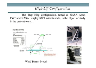
- 10. High-Lift Configuration The Trap-Wing configuration, tested at NASA Ames PWT and NASA Langley SWT wind tunnels, is the object of study in the present work. Wind Tunnel Model
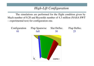
- 11. High-Lift Configuration The simulations are performed for the flight condition given by Mach number of 0.20 and Reynolds number of 4.3 million (NASA SWT â experimental test) for configuration one. Configuration Flap Spanwise Slat Deflec. Flap Deflec. 01 full 30 25
- 12. Outline Objectives Theoretical and Numerical Formulations High-Lift Configuration Mesh Generation Results Conclusions
- 13. Outline Objectives Theoretical and Numerical Formulations High-Lift Configuration Mesh Generation Results Conclusions
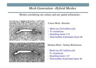
- 14. Mesh Generation âHybrid Meshes Meshes considering one surface and one spatial refinements. Coarse Mesh - Baseline - Mesh size 24.8 million cells - Y+ around one - Stretching factor 1.15 - Total number of prismatic layers 46 Medium Mesh â Surface Refinement - Mesh size 49.3 million cells - Y+ around one - Stretching factor 1.15 - Total number of prismatic layers 46
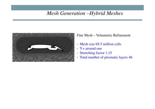
- 15. Mesh Generation âHybrid Meshes Fine Mesh â Volumetric Refinement - Mesh size 69.5 million cells - Y+ around one - Stretching factor 1.15 - Total number of prismatic layers 46
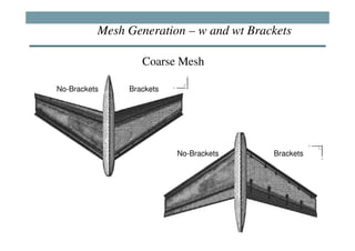
- 16. Mesh Generation â w and wt Brackets Coarse Mesh No-Brackets Brackets No-Brackets Brackets
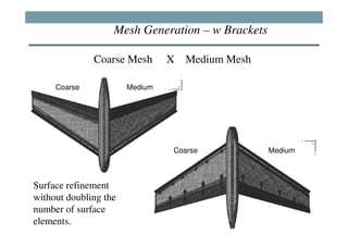
- 17. Mesh Generation â w Brackets Coarse Mesh X Medium Mesh Coarse Medium Coarse Medium Surface refinement without doubling the number of surface elements.
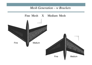
- 18. Mesh Generation â w Brackets Fine Mesh X Medium Mesh Fine Medium Fine Medium
- 19. Outline Objectives Theoretical and Numerical Formulations High-Lift Configuration Mesh Generation Results Conclusions
- 20. Outline Objectives Theoretical and Numerical Formulations High-Lift Configuration Mesh Generation Results Conclusions
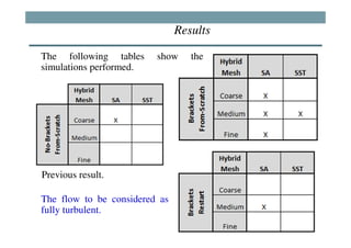
- 21. Results The following tables show the simulations performed. Previous result. The flow to be considered as fully turbulent.
- 22. Outline Objectives Theoretical and Numerical Formulations High-Lift Configuration Mesh Generation Results Coarse Mesh Medium Mesh Fine Mesh Conclusions
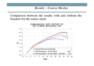
- 23. Results â Coarse Meshes Comparison between the results with and without the brackets for the coarse mesh
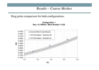
- 24. Results â Coarse Meshes Drag polar comparison for both configurations.
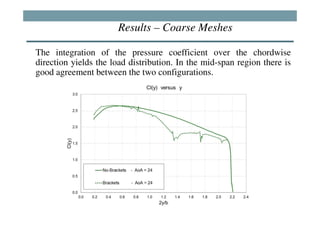
- 25. Results â Coarse Meshes The integration of the pressure coefficient over the chordwise direction yields the load distribution. In the mid-span region there is good agreement between the two configurations.
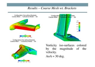
- 26. Results â Coarse Mesh wt. Brackets Vorticity iso-surfaces colored by the magnitude of the velocity. AoA = 30 deg.
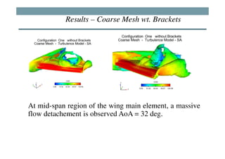
- 27. Results â Coarse Mesh wt. Brackets At mid-span region of the wing main element, a massive flow detachement is observed AoA = 32 deg.
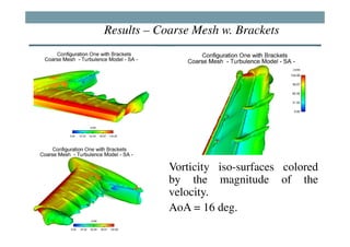
- 28. Results â Coarse Mesh w. Brackets Vorticity iso-surfaces colored by the magnitude of the velocity. AoA = 16 deg.
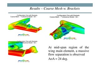
- 29. Results â Coarse Mesh w. Brackets At mid-span region of the wing main element, a massive flow separation is observed AoA = 24 deg.
- 30. Outline Objectives Theoretical and Numerical Formulations High-Lift Configuration Mesh Generation Results Coarse Mesh Medium Mesh Fine Mesh Conclusions
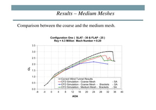
- 31. Results â Medium Meshes Comparison between the coarse and the medium mesh.
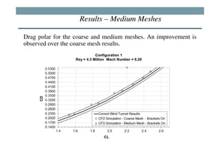
- 32. Results â Medium Meshes Drag polar for the coarse and medium meshes. An improvement is observed over the coarse mesh results.
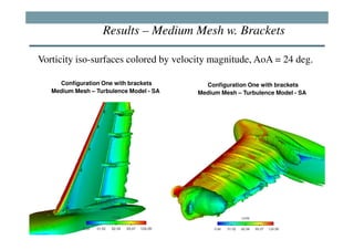
- 33. Results â Medium Mesh w. Brackets Vorticity iso-surfaces colored by velocity magnitude, AoA = 24 deg. Configuration One with brackets Configuration One with brackets Medium Mesh â Turbulence Model - SA Medium Mesh â Turbulence Model - SA
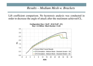
- 34. Results â Medium Mesh w. Brackets Lift coefficient comparison. No hysteresis analysis was conducted in order to decrease the angle of attack after the maximum achieved CL.
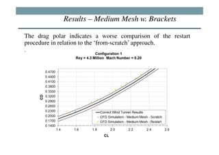
- 35. Results â Medium Mesh w. Brackets The drag polar indicates a worse comparison of the restart procedure in relation to the âfrom-scratchâ approach. .
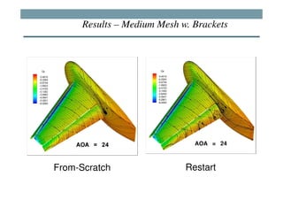
- 36. Results â Medium Mesh w. Brackets From-Scratch Restart
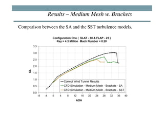
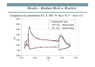
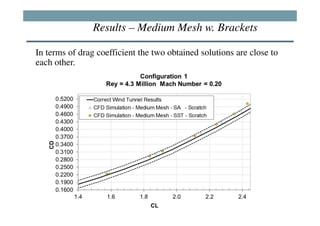
- 37. Results â Medium Mesh w. Brackets Comparison between the SA and the SST turbulence models.
- 38. Results â Medium Mesh w. Brackets Comparison Cp distribution SA X SST @ Eta = 0.17 - AoA =13
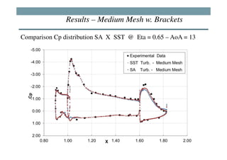
- 39. Results â Medium Mesh w. Brackets Comparison Cp distribution SA X SST @ Eta = 0.65 â AoA = 13
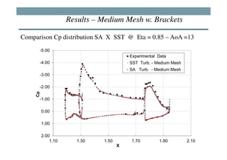
- 40. Results â Medium Mesh w. Brackets Comparison Cp distribution SA X SST @ Eta = 0.85 â AoA =13
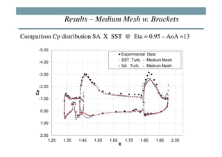
- 41. Results â Medium Mesh w. Brackets Comparison Cp distribution SA X SST @ Eta = 0.95 â AoA =13
- 42. Results â Medium Mesh w. Brackets In terms of drag coefficient the two obtained solutions are close to each other.
- 43. Outline Objectives Theoretical and Numerical Formulations High-Lift Configuration Mesh Generation Results Coarse Mesh Medium Mesh Fine Mesh Conclusions
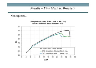
- 44. Results â Fine Mesh w. Brackets Not expected...
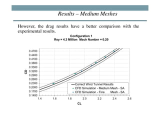
- 45. Results â Medium Meshes However, the drag results have a better comparison with the experimental results.
- 46. Conclusions âĒ The mesh assumed as coarse presented a very premature stall. âĒ The surface mesh refinement provided an improvement in the aerodynamic coefficients. âĒ The volumetric refinement presented an unexpected result which decreased the stall angle of attack and the maximum CL. âĒ The different turbulence models are generating very different flow pattern. âĒ There is a need to continue the studies with a more systematic procedure to perform the mesh generation.