applications of diode - clipper and clamper circuits.pdf
0 likes73 views
Chapter 4 discusses common diode applications, focusing on clippers and clampers. Clippers are circuits that eliminate portions of waveforms, categorized into series and shunt types, while clampers shift waveforms above or below a reference voltage. Additionally, biased versions of both clippers and clampers allow for adjustable clipping or shifting based on a DC biasing source.
1 of 21
Download to read offline
Ad
Recommended
Clippers_and_Clampers.pptx
Clippers_and_Clampers.pptxSIVA NAGI REDY KALLI
╠²
Clippers and clampers use diodes to limit or shift signal voltages. There are four basic clipper configurations that use diodes in either series or parallel to clip either the positive or negative portions of a signal. Clampers use a diode along with a capacitor and resistor to shift a signal voltage to a different DC level without distorting its shape. Common applications of clippers and clampers include transient protection, amplitude modulation detection, and DC restoration in television receivers.Analog electronic circuit
Analog electronic circuitmohamed albanna
╠²
1. The document discusses the principles of operation of p-n junction diodes and their use in analog electronic circuits. It describes how a diode only conducts current in one direction when forward biased and acts as an open switch when reverse biased.
2. Diode clipper circuits are introduced which can clip off portions of an input signal by only allowing the signal to pass through the diode when above or below a certain threshold set by a bias voltage. Parallel and series clipper configurations are examined along with their input-output characteristics.
3. Double-ended clipper circuits are described which can clip both the positive and negative portions of a signal simultaneously using two back-to-back diodes biased to conduct onlyPeakdetector
PeakdetectorManjunath Achari
╠²
The document summarizes experiments on non-linear op-amp circuits, including a comparator, half-wave rectifier, and clipper. It provides the objectives, required equipment, pre-lab questions, and theoretical explanations of how each circuit works. The experiments involve assembling the circuits using op-amps and diodes, observing input and output waveforms on an oscilloscope, and analyzing the output characteristics as circuit parameters are varied. Key points covered include how comparators detect voltage levels, how rectifiers and clippers modify input signals based on reference voltages, and the roles of op-amp gain and diode properties.Diodes vi characteries
Diodes vi characteriesManikandan Chinnadurai
╠²
1. A pn junction diode allows current to flow easily in one direction but blocks current in the reverse direction.
2. When forward biased, holes flow from the p-type to the n-type region and electrons flow the other way, allowing current flow. When reverse biased, very few carriers cross the junction.
3. Diode applications include rectification, clipping signals, and clamping signals to different voltage levels. Rectification converts AC to DC, while clipping and clamping modify signal levels.Diode Applications.pptx
Diode Applications.pptxShrutiSharma485933
╠²
Diode applications include rectifiers, clippers, clampers, voltage multipliers, and Zener voltage regulators. Rectifiers convert AC to pulsating DC and are classified as half-wave or full-wave. Clippers control waveform shape by removing portions. Clampers combine a diode and capacitor to clamp an AC signal to a DC level. Voltage multipliers produce an output DC voltage that is an integer multiple of the peak AC input. Zener diodes act as voltage regulators, providing a constant output voltage at their breakdown voltage.Lec-4.pdf
Lec-4.pdfGollapalli Sreenivasulu
╠²
This document provides information on various electronics concepts including:
- Clampers shift an input signal to a different DC level without changing its waveform using a diode and capacitor.
- Voltage multipliers like doublers and triplers use diode-capacitor combinations to add stored voltages and produce an output voltage that is a multiple of the input peak voltage.
- Zener diodes are designed to operate in reverse breakdown and maintain a constant voltage regardless of current, making them useful for voltage regulation applications.clipper and clamper are the application of semiconductor diodes
clipper and clamper are the application of semiconductor diodesDebasishMohanta16
╠²
clipper and clamper are the application of semiconductor diodes.JUNCTION DIODE APPLICATIONS
JUNCTION DIODE APPLICATIONSAsmita Bhagdikar
╠²
Diode applications include rectifier circuits, which use diodes to convert alternating current (AC) to direct current (DC). A half-wave rectifier uses a single diode to allow only one half of the AC cycle to pass, while full-wave rectifiers like the bridge rectifier use four diodes to pass both halves of the cycle. Diodes can also be used in clipping circuits to clip portions of a signal waveform, and in clamping circuits to clamp a signal to a specific DC level. Zener diodes operate in reverse bias at the Zener voltage and are used to set reference voltages.Electronics 1 : Chapter # 04 : Diode Applications and Types
Electronics 1 : Chapter # 04 : Diode Applications and TypesSk_Group
╠²
The document discusses various diode applications and types, explaining load line analysis, series and parallel configurations, and different rectification methods like half-wave and full-wave. It also covers Zener diodes as voltage regulators, clipper and clamper circuits, as well as voltage multiplier circuits for stepping up output voltage. Additionally, practical applications of rectifier and Zener circuits are highlighted for converting AC to DC and providing protection in electronic circuits.Diode_Clipper_Clamper_Voltage_Multiplier.pptx
Diode_Clipper_Clamper_Voltage_Multiplier.pptxIrfanSiddiqui50
╠²
This document discusses clipper and clamper circuits which use diodes, capacitors and resistors. Clipper circuits clip off a portion of the waveform from an input signal and come in series and parallel configurations for positive or negative clipping. Clamper circuits shift an entire signal to a different DC level. Specific examples are given of series positive and negative clipper circuits and parallel positive and negative clipper circuits. Clamper circuits are also explained showing how a capacitor can clamp the input signal to a DC level set by the voltage source or diode.Clampers and clippers
Clampers and clippersSARITHA REDDY
╠²
This document discusses different types of non-linear circuits including clamping circuits, clippers, and peak detectors. Clamping circuits adjust the DC level of a waveform without changing its shape or amplitude. Clippers clip off portions of the input waveform above or below a reference voltage. Peak detectors track the input signal until detecting a peak value, then hold that value to provide voltage memory of the peak. Circuit diagrams and example waveforms are provided to illustrate the operation of these different non-linear circuits.Clipper and clampers
Clipper and clampersAkanksha arora
╠²
The document discusses clippers and clampers, focusing on their definitions, circuit components, classifications, and applications. Clippers are wave-shaping circuits that either remove part of an input signal or limit its amplitude, while clampers shift the signal's level without altering its shape. Various types of clippers and clampers are explained, including their configurations, benefits, drawbacks, and applications in electronics, such as television and radar systems.Diode Applications rectifires, and .pptx
Diode Applications rectifires, and .pptxshilpa637874
╠²
The document discusses diode applications, focusing on rectification, which converts alternating current (AC) to direct current (DC) using half-wave and full-wave rectifiers. It explains how half-wave rectifiers allow only one half-cycle of an AC waveform to pass, while full-wave rectifiers convert both cycles of AC into a pulsating DC output. Additionally, it covers filter circuits used to smooth the output, including capacitor filters, and analyzes different rectifier configurations and their performance.ELECTRONICS
ELECTRONICSshahzadebaujiti
╠²
This document discusses electronics topics including conductors, insulators, semiconductors, intrinsic and extrinsic semiconductors, doping, N-type and P-type semiconductors, PN junctions, rectifiers, transistors, operational amplifiers, and logic gates. It provides details on:
- How conductors allow free electron flow while insulators do not, with semiconductors in between.
- The doping process used to create N-type and P-type extrinsic semiconductors.
- How a PN junction forms and its use as a rectifier, allowing current to flow more easily in one direction.
- The basic transistor configuration377275109-Ch-2-Uncontrolled-Rectifiers-Autosaved.pptx
377275109-Ch-2-Uncontrolled-Rectifiers-Autosaved.pptxpriyakunduq
╠²
This document discusses uncontrolled rectifiers, which use diodes to convert alternating current (AC) to direct current (DC). It covers the operation and analysis of single-phase half-wave and full-wave rectifiers, as well as three-phase rectifiers, with both resistive and inductive loads. Key points covered include the output voltage and current calculations, effects of adding capacitors or inductors, and how source inductance can affect rectifier operation. The objectives are to understand different rectifier circuits and analyze their performance parameters.unit 3.pptx
unit 3.pptxRanganayakiRamkumar1
╠²
The document discusses different types of oscillators and signal processing circuits. It describes a sinusoidal oscillator that produces a sine wave output from a DC input source. It also describes an RC phase shift oscillator that uses an op-amp in inverting mode along with RC sections to provide a total phase shift of 360 degrees. Additionally, it discusses a Wien bridge oscillator that uses an op-amp in non-inverting mode along with a feedback network balanced to provide a total phase shift of 0 degrees.Electronic devices circuits
Electronic devices circuitssudeep kumar
╠²
The document discusses electronic devices and circuits, specifically focusing on PN diodes. It describes the theory of PN junctions, how a PN junction forms a diode, and the characteristics and properties of PN diode currents and voltages. It discusses topics like volt-amp characteristics, temperature effects, and switching times of PN diodes. It also provides explanations and circuit diagrams of half-wave and full-wave rectifiers, zener diodes, liquid crystal displays, and series voltage regulators.DIODE APPLICATIONS .pdf
DIODE APPLICATIONS .pdfssuserb29892
╠²
This document provides an overview of diode applications and circuit analysis techniques. It discusses load line analysis and how it is used to determine the operating point of a diode circuit. It also covers rectification circuits including half-wave and full-wave rectifiers using a center-tapped transformer or bridge configuration. The document examines peak inverse voltage ratings, filter circuits to reduce ripple voltage from rectifiers, and voltage regulators. Examples are provided to illustrate key concepts like load line analysis, rectifier output voltage calculations, and determining minimum diode ratings.Clippers AND Clampers
Clippers AND ClampersJUNAID SK
╠²
This document describes the theory, circuit diagrams, and experimental procedures for studying clipping and clamping circuits using diodes. Clipping circuits are used to clip off portions of an input waveform above or below certain voltage levels. Clamping circuits add or subtract a DC voltage to a waveform without changing its shape. The document provides details on setting up series and shunt clipping circuits, as well as positive, negative, and double clipping circuits. It also covers positive, negative, and double clamping circuits and how they operate to clamp the input signal at different voltage levels. Procedures for observing input and output waveforms on an oscilloscope are included.Unit-III Electronics.pdf
Unit-III Electronics.pdfSachinNaagar4
╠²
This document provides an overview of electronic devices and circuits. It discusses semiconductors like silicon and germanium and how they are doped to create p-type and n-type materials. The junction diode is described as the simplest electronic device, formed by joining p-type and n-type silicon. Diode applications in rectifiers and clipping/clamping circuits are explained. The document also covers LEDs and provides the junction diode current equation.03
03MD Jakaria
╠²
This document summarizes an experiment on diode clipping and clamping circuits. It includes the objectives, equipment used, circuit diagrams of clipping and clamping circuits tested, and a report of the results. The report explains that clipping cuts off part of a signal waveform while clamping shifts a signal to a different DC level without changing its shape. It analyzes the operation of the clipping and clamping circuits and discusses the output waveforms observed on an oscilloscope. It notes some differences between the ideal circuit behavior described and actual results due to non-ideal diode characteristics.Lab - 03
Lab - 03MD Jakaria
╠²
This document summarizes an experiment on diode clipping and clamping circuits. It includes the objectives, equipment used, circuit diagrams of clipping and clamping circuits tested, and results from those circuits. Key findings are: 1) clipping circuits cut off portions of the input signal above or below certain voltage thresholds, while clamping circuits shift the entire signal up or down by a fixed amount. 2) In a clipping circuit, diodes allow the output to follow the input until a threshold is reached, then clamp the output at that level. 3) A clamping circuit uses a capacitor, diode, and resistor to shift the entire signal down by twice the peak input voltage.║▌║▌▀Ż_02_Chapter electrical circuit_6.pptx
║▌║▌▀Ż_02_Chapter electrical circuit_6.pptxmoslahuddin2022
╠²
The document provides an overview of semiconductor diodes, specifically focusing on their function as rectifiers that convert alternating current (AC) to direct current (DC). It explains the concepts of forward and reverse bias, the characteristics of diode resistance, and the operation of half-wave rectification with associated applications, including the advantages and disadvantages of using crystal diodes. Additionally, it includes mathematical examples related to power and efficiency calculations for half-wave rectifiers.Lect 05 Diodes and applications - Part2.pptx
Lect 05 Diodes and applications - Part2.pptxPedroErenciaMillan
╠²
This document provides a summary of Lecture 05 which covered diode applications and special diode types. It discusses how diodes can be used in rectifier circuits to convert AC to DC for powering electronics. Different rectifier circuit types are examined including half-wave, full-wave, and bridge rectifiers. Filter capacitors are also discussed for smoothing the pulsating DC output of rectifiers. Additional applications like limiting, clamping, and voltage doubling circuits are covered. Finally, special diode types such as LEDs, photodiodes, Schottky diodes, varactor diodes, and Zener diodes are introduced.L6 and L7 full wave rectifier, PIV.ppt
L6 and L7 full wave rectifier, PIV.pptKennyG13
╠²
The document discusses different types of rectifiers including half-wave and full-wave rectifiers. It describes how full-wave rectifiers using a center-tapped transformer or a bridge rectifier circuit can produce an output voltage during both half-cycles of the input signal. It also defines key terms like peak inverse voltage (PIV) and duty cycle. Examples are provided to calculate voltage and current values for different rectifier circuits and to determine the transformer turns ratio and PIV for center-tapped and bridge full-wave rectifiers.L6 and L7 full wave rectifier, PIV.ppt
L6 and L7 full wave rectifier, PIV.pptAnveshYamagani
╠²
The document discusses different types of rectifiers including half-wave and full-wave rectifiers. It describes how full-wave rectifiers can be built using either a center-tapped transformer or a bridge rectifier. It also defines key terms like peak inverse voltage (PIV) and duty cycle. Examples are provided to calculate voltage and current values for different rectifier circuits and to determine the PIV for half-wave and full-wave rectifiers based on the input voltage and diode cut-in voltage.Clipping Circuits
Clipping Circuits─Ük┼é├żv├Į├Ż K├╝m├ż┼Ģ
╠²
Clipping and clamping circuits use diodes to modify input waveforms. Clipping circuits cut off portions of the waveform that exceed a threshold voltage, while clamping circuits shift the DC level of a waveform up or down. Basic clipping circuits use diodes, resistors, and batteries, with the diode orientation and battery voltage determining if it is a positive or negative clipper. Positive clippers cut off positive portions of the input, while negative clippers cut off negative portions. Clipping can be done in either a series or parallel configuration.Ankit singh
Ankit singhVipul Pratap Singh
╠²
This document discusses different types of diodes used in electronics. It describes p-n junction diodes, Zener diodes, light emitting diodes, and photo diodes. It explains how p-n junction diodes are made using silicon or germanium semiconductor material with added impurities to create n-type and p-type regions. When these regions are attached, a p-n junction is formed. It also discusses half-wave and full-wave rectifiers used to convert AC to DC, and how Zener diodes allow current to flow in both directions above a breakdown voltage.More Related Content
Similar to applications of diode - clipper and clamper circuits.pdf (20)
Electronics 1 : Chapter # 04 : Diode Applications and Types
Electronics 1 : Chapter # 04 : Diode Applications and TypesSk_Group
╠²
The document discusses various diode applications and types, explaining load line analysis, series and parallel configurations, and different rectification methods like half-wave and full-wave. It also covers Zener diodes as voltage regulators, clipper and clamper circuits, as well as voltage multiplier circuits for stepping up output voltage. Additionally, practical applications of rectifier and Zener circuits are highlighted for converting AC to DC and providing protection in electronic circuits.Diode_Clipper_Clamper_Voltage_Multiplier.pptx
Diode_Clipper_Clamper_Voltage_Multiplier.pptxIrfanSiddiqui50
╠²
This document discusses clipper and clamper circuits which use diodes, capacitors and resistors. Clipper circuits clip off a portion of the waveform from an input signal and come in series and parallel configurations for positive or negative clipping. Clamper circuits shift an entire signal to a different DC level. Specific examples are given of series positive and negative clipper circuits and parallel positive and negative clipper circuits. Clamper circuits are also explained showing how a capacitor can clamp the input signal to a DC level set by the voltage source or diode.Clampers and clippers
Clampers and clippersSARITHA REDDY
╠²
This document discusses different types of non-linear circuits including clamping circuits, clippers, and peak detectors. Clamping circuits adjust the DC level of a waveform without changing its shape or amplitude. Clippers clip off portions of the input waveform above or below a reference voltage. Peak detectors track the input signal until detecting a peak value, then hold that value to provide voltage memory of the peak. Circuit diagrams and example waveforms are provided to illustrate the operation of these different non-linear circuits.Clipper and clampers
Clipper and clampersAkanksha arora
╠²
The document discusses clippers and clampers, focusing on their definitions, circuit components, classifications, and applications. Clippers are wave-shaping circuits that either remove part of an input signal or limit its amplitude, while clampers shift the signal's level without altering its shape. Various types of clippers and clampers are explained, including their configurations, benefits, drawbacks, and applications in electronics, such as television and radar systems.Diode Applications rectifires, and .pptx
Diode Applications rectifires, and .pptxshilpa637874
╠²
The document discusses diode applications, focusing on rectification, which converts alternating current (AC) to direct current (DC) using half-wave and full-wave rectifiers. It explains how half-wave rectifiers allow only one half-cycle of an AC waveform to pass, while full-wave rectifiers convert both cycles of AC into a pulsating DC output. Additionally, it covers filter circuits used to smooth the output, including capacitor filters, and analyzes different rectifier configurations and their performance.ELECTRONICS
ELECTRONICSshahzadebaujiti
╠²
This document discusses electronics topics including conductors, insulators, semiconductors, intrinsic and extrinsic semiconductors, doping, N-type and P-type semiconductors, PN junctions, rectifiers, transistors, operational amplifiers, and logic gates. It provides details on:
- How conductors allow free electron flow while insulators do not, with semiconductors in between.
- The doping process used to create N-type and P-type extrinsic semiconductors.
- How a PN junction forms and its use as a rectifier, allowing current to flow more easily in one direction.
- The basic transistor configuration377275109-Ch-2-Uncontrolled-Rectifiers-Autosaved.pptx
377275109-Ch-2-Uncontrolled-Rectifiers-Autosaved.pptxpriyakunduq
╠²
This document discusses uncontrolled rectifiers, which use diodes to convert alternating current (AC) to direct current (DC). It covers the operation and analysis of single-phase half-wave and full-wave rectifiers, as well as three-phase rectifiers, with both resistive and inductive loads. Key points covered include the output voltage and current calculations, effects of adding capacitors or inductors, and how source inductance can affect rectifier operation. The objectives are to understand different rectifier circuits and analyze their performance parameters.unit 3.pptx
unit 3.pptxRanganayakiRamkumar1
╠²
The document discusses different types of oscillators and signal processing circuits. It describes a sinusoidal oscillator that produces a sine wave output from a DC input source. It also describes an RC phase shift oscillator that uses an op-amp in inverting mode along with RC sections to provide a total phase shift of 360 degrees. Additionally, it discusses a Wien bridge oscillator that uses an op-amp in non-inverting mode along with a feedback network balanced to provide a total phase shift of 0 degrees.Electronic devices circuits
Electronic devices circuitssudeep kumar
╠²
The document discusses electronic devices and circuits, specifically focusing on PN diodes. It describes the theory of PN junctions, how a PN junction forms a diode, and the characteristics and properties of PN diode currents and voltages. It discusses topics like volt-amp characteristics, temperature effects, and switching times of PN diodes. It also provides explanations and circuit diagrams of half-wave and full-wave rectifiers, zener diodes, liquid crystal displays, and series voltage regulators.DIODE APPLICATIONS .pdf
DIODE APPLICATIONS .pdfssuserb29892
╠²
This document provides an overview of diode applications and circuit analysis techniques. It discusses load line analysis and how it is used to determine the operating point of a diode circuit. It also covers rectification circuits including half-wave and full-wave rectifiers using a center-tapped transformer or bridge configuration. The document examines peak inverse voltage ratings, filter circuits to reduce ripple voltage from rectifiers, and voltage regulators. Examples are provided to illustrate key concepts like load line analysis, rectifier output voltage calculations, and determining minimum diode ratings.Clippers AND Clampers
Clippers AND ClampersJUNAID SK
╠²
This document describes the theory, circuit diagrams, and experimental procedures for studying clipping and clamping circuits using diodes. Clipping circuits are used to clip off portions of an input waveform above or below certain voltage levels. Clamping circuits add or subtract a DC voltage to a waveform without changing its shape. The document provides details on setting up series and shunt clipping circuits, as well as positive, negative, and double clipping circuits. It also covers positive, negative, and double clamping circuits and how they operate to clamp the input signal at different voltage levels. Procedures for observing input and output waveforms on an oscilloscope are included.Unit-III Electronics.pdf
Unit-III Electronics.pdfSachinNaagar4
╠²
This document provides an overview of electronic devices and circuits. It discusses semiconductors like silicon and germanium and how they are doped to create p-type and n-type materials. The junction diode is described as the simplest electronic device, formed by joining p-type and n-type silicon. Diode applications in rectifiers and clipping/clamping circuits are explained. The document also covers LEDs and provides the junction diode current equation.03
03MD Jakaria
╠²
This document summarizes an experiment on diode clipping and clamping circuits. It includes the objectives, equipment used, circuit diagrams of clipping and clamping circuits tested, and a report of the results. The report explains that clipping cuts off part of a signal waveform while clamping shifts a signal to a different DC level without changing its shape. It analyzes the operation of the clipping and clamping circuits and discusses the output waveforms observed on an oscilloscope. It notes some differences between the ideal circuit behavior described and actual results due to non-ideal diode characteristics.Lab - 03
Lab - 03MD Jakaria
╠²
This document summarizes an experiment on diode clipping and clamping circuits. It includes the objectives, equipment used, circuit diagrams of clipping and clamping circuits tested, and results from those circuits. Key findings are: 1) clipping circuits cut off portions of the input signal above or below certain voltage thresholds, while clamping circuits shift the entire signal up or down by a fixed amount. 2) In a clipping circuit, diodes allow the output to follow the input until a threshold is reached, then clamp the output at that level. 3) A clamping circuit uses a capacitor, diode, and resistor to shift the entire signal down by twice the peak input voltage.║▌║▌▀Ż_02_Chapter electrical circuit_6.pptx
║▌║▌▀Ż_02_Chapter electrical circuit_6.pptxmoslahuddin2022
╠²
The document provides an overview of semiconductor diodes, specifically focusing on their function as rectifiers that convert alternating current (AC) to direct current (DC). It explains the concepts of forward and reverse bias, the characteristics of diode resistance, and the operation of half-wave rectification with associated applications, including the advantages and disadvantages of using crystal diodes. Additionally, it includes mathematical examples related to power and efficiency calculations for half-wave rectifiers.Lect 05 Diodes and applications - Part2.pptx
Lect 05 Diodes and applications - Part2.pptxPedroErenciaMillan
╠²
This document provides a summary of Lecture 05 which covered diode applications and special diode types. It discusses how diodes can be used in rectifier circuits to convert AC to DC for powering electronics. Different rectifier circuit types are examined including half-wave, full-wave, and bridge rectifiers. Filter capacitors are also discussed for smoothing the pulsating DC output of rectifiers. Additional applications like limiting, clamping, and voltage doubling circuits are covered. Finally, special diode types such as LEDs, photodiodes, Schottky diodes, varactor diodes, and Zener diodes are introduced.L6 and L7 full wave rectifier, PIV.ppt
L6 and L7 full wave rectifier, PIV.pptKennyG13
╠²
The document discusses different types of rectifiers including half-wave and full-wave rectifiers. It describes how full-wave rectifiers using a center-tapped transformer or a bridge rectifier circuit can produce an output voltage during both half-cycles of the input signal. It also defines key terms like peak inverse voltage (PIV) and duty cycle. Examples are provided to calculate voltage and current values for different rectifier circuits and to determine the transformer turns ratio and PIV for center-tapped and bridge full-wave rectifiers.L6 and L7 full wave rectifier, PIV.ppt
L6 and L7 full wave rectifier, PIV.pptAnveshYamagani
╠²
The document discusses different types of rectifiers including half-wave and full-wave rectifiers. It describes how full-wave rectifiers can be built using either a center-tapped transformer or a bridge rectifier. It also defines key terms like peak inverse voltage (PIV) and duty cycle. Examples are provided to calculate voltage and current values for different rectifier circuits and to determine the PIV for half-wave and full-wave rectifiers based on the input voltage and diode cut-in voltage.Clipping Circuits
Clipping Circuits─Ük┼é├żv├Į├Ż K├╝m├ż┼Ģ
╠²
Clipping and clamping circuits use diodes to modify input waveforms. Clipping circuits cut off portions of the waveform that exceed a threshold voltage, while clamping circuits shift the DC level of a waveform up or down. Basic clipping circuits use diodes, resistors, and batteries, with the diode orientation and battery voltage determining if it is a positive or negative clipper. Positive clippers cut off positive portions of the input, while negative clippers cut off negative portions. Clipping can be done in either a series or parallel configuration.Ankit singh
Ankit singhVipul Pratap Singh
╠²
This document discusses different types of diodes used in electronics. It describes p-n junction diodes, Zener diodes, light emitting diodes, and photo diodes. It explains how p-n junction diodes are made using silicon or germanium semiconductor material with added impurities to create n-type and p-type regions. When these regions are attached, a p-n junction is formed. It also discusses half-wave and full-wave rectifiers used to convert AC to DC, and how Zener diodes allow current to flow in both directions above a breakdown voltage.More from ragustilo27 (14)
ANGLE MODULATION AND TRANSMISSION (FM AND PM).pdf
ANGLE MODULATION AND TRANSMISSION (FM AND PM).pdfragustilo27
╠²
angle modulation and transmission in electronic communicationDerivatives-of-Exponential-and-Logarithmic-Functions-and-Logarithmic-Differen...
Derivatives-of-Exponential-and-Logarithmic-Functions-and-Logarithmic-Differen...ragustilo27
╠²
The document discusses derivatives of exponential and logarithmic functions, providing formulas and illustrative examples for both types of derivatives. It introduces logarithmic differentiation as a method for differentiating non-constant functions, outlining a step-by-step approach with multiple examples and practice problems. The content aims to cultivate understanding and application of these differentiation techniques.Curve Tracing using Maxima and Minima.pptx
Curve Tracing using Maxima and Minima.pptxragustilo27
╠²
The document outlines the concepts of critical numbers and critical points in polynomial functions, emphasizing their importance in determining extrema, including both relative and absolute maxima and minima. It details methods for finding critical points through derivatives and the subsequent steps to ascertain extrema within an interval, utilizing both first and second derivative tests. Additionally, it describes the procedure for sketching polynomial curves by identifying intersection points with axes and analyzing concavity and points of inflection.transfer function for control systems .pptx
transfer function for control systems .pptxragustilo27
╠²
The document discusses the use of the Laplace transform in control systems, explaining how it transforms differential equations from the time domain to algebraic equations in the frequency domain. It also covers the concept of transfer functions, including their poles and zeros, and how these are represented in block diagrams to model complex systems. Finally, it highlights the significance of these diagrams in simplifying and illustrating the transfer functions of control system elements.Lecture-11-derivatives of Parametric-Functions.pptx
Lecture-11-derivatives of Parametric-Functions.pptxragustilo27
╠²
The document discusses parametric functions, which relate two variables through a third variable known as a parameter. It explains how to differentiate these functions, providing formulas for first, second, and third derivatives using parametric differentiation. Examples are included to illustrate how to find the derivatives of parametric equations.Lecture-12-Slope-tangents-and-normals.pptx
Lecture-12-Slope-tangents-and-normals.pptxragustilo27
╠²
The document discusses the concepts of slope, tangent lines, and normal lines related to polynomial curves. It includes examples illustrating how to find the slope at specific points, derive equations for tangent and normal lines, and identify points where tangents are parallel to a given line. Additional assignments are also provided for practice in determining tangent and normal lines at specified coordinates.LECTURE-5-CAPITALIZED-COST-AMORTIZATION-GRADIENT.pptx
LECTURE-5-CAPITALIZED-COST-AMORTIZATION-GRADIENT.pptxragustilo27
╠²
The document discusses capitalized cost as the sum of initial expenses and present worth of future costs in property management, emphasizing its role in comparing alternatives. It details amortization methods for debt repayment, including a semiannual payment example for a loan with specific interest rates and an amortization schedule. Finally, it introduces uniform arithmetic gradients in economic analysis, showcasing cash flow trends that increase or decrease uniformly over time.intro to CONTROL STRUCTURES 1 for C++.pptx
intro to CONTROL STRUCTURES 1 for C++.pptxragustilo27
╠²
The document discusses control structures in C++ programming, focusing on selection mechanisms such as one-way and two-way statements. It covers relational and logical operators, their precedence, and the use of conditional operators and switch structures. Key points include the evaluation of logical expressions, the formation of compound statements, and the importance of proper syntax to avoid semantic errors.Introduction and history of Computers.pptx
Introduction and history of Computers.pptxragustilo27
╠²
The document provides an overview of the history of computers, their systems, and programming languages, explaining key milestones from the abacus to modern-day programming languages like C++. It details the components of a computer, including hardware and software, and explains the problem-solving processes involved in programming, including structured and object-oriented design methodologies. The summary emphasizes the importance of algorithms and the evolution of programming languages as essential tools for software development.ENMATH11E-2024-2025-1st-Sem-HANDOUTS-1-NUMBERS-AND-OPERATIONS-Copy.pptx
ENMATH11E-2024-2025-1st-Sem-HANDOUTS-1-NUMBERS-AND-OPERATIONS-Copy.pptxragustilo27
╠²
The document focuses on the basic concepts of numbers and operations, including various types of numbers, field axioms of real numbers, and operations like addition, subtraction, multiplication, and division. It covers fractions, including types of fractions and how to perform operations with them, as well as exponents and radicals. The lecture emphasizes the order of operations using acronyms like PEMDAS and GEMS.Lecture 2- BASIC LIMITS and INDETERMINATE FORM.pptx
Lecture 2- BASIC LIMITS and INDETERMINATE FORM.pptxragustilo27
╠²
The document discusses the definition of limits and explains how to estimate limits numerically and using graphs. It provides various examples of functions to illustrate the concept of limits, including left-hand and right-hand limits, as well as situations where limits do not exist. Additionally, it covers analytical evaluation of limits with specific examples and emphasizes the importance of comparing left and right limits for a limit to exist.Ad
Recently uploaded (20)
A Cluster-Based Trusted Secure Multipath Routing Protocol for Mobile Ad Hoc N...
A Cluster-Based Trusted Secure Multipath Routing Protocol for Mobile Ad Hoc N...IJCNCJournal
╠²
Mobile Ad Hoc Network (MANET) is a self-organizing and flexible system. MANET systems manage sensitive data from many distinct applications in various domains. Its dynamic nature increases its vulnerability to numerous types of security threats. Many of the present approaches using indirect approaches provide false approximations of trust degrees. It is significantly required a good routing system that meets Quality of Service (QoS) standards and enhances network performance. In this paper purposed cluster-based trustworthy safe multipath routing (CTSMP-Routing) for mobile ad hoc networks (MANETs). Load balancing challenge is addressed by using a modified proportional topology optimization (MPTO) approach using geographical data related to network nodes. The Enhanced Seeker Search Optimization (ESSO) approach is used to compute trust degrees after the clustering phase considering numerous network constraints including node mobility, received signal strength, energy consumption, and cooperation rate. Assumed to be the service node, the node showing the highest degree of trust manages inter-cluster routing. We have developed a hybrid soft computing approach termed the multi-layer deep recurrent neural network (ML-DRNN) to enhance the optimal path-finding process. This method selects, among many routes between source and destination nodes, the best one quickly. The outcomes of this paper demonstrate that CTSMP-Routing provides effective protection against several attack paths within the MANET environment and displays better performance in regard to quality of service (QoS) requirements.Stay Safe Women Security Android App Project Report.pdf
Stay Safe Women Security Android App Project Report.pdfKamal Acharya
╠²
WomenŌĆÖs security is a critical issue in todayŌĆÖs world and itŌĆÖs very much needed for every individual
to be acting over such an issue. This document describes a GPS based ŌĆ£Women Security System''
that provides the combination of GPS devices as well as provide alerts and messages with an
emergency button trigger whenever somebody is in trouble They might not have so much time, all
that they have to do is generate a distress emergency signal by shaking up their phone. Our system
provides a realizable, cost effective solution to problem detection. Nowdays due to recently
happened cases such as rape by drivers or colleagues, burglary etc., women security, especially
women security has become the foremost priority of the world. System uses the Global Positioning
System (GPS) technology to find out the location of women. The information of women's position
provided by the device can be viewed on Google maps using Internet or specialized software. The
companies are looking for-ward to the security problem and require a system that will efficiently
evaluate the problem of women security working in night shifts, traveling alone. We focus on the
proposed model that can be used to deal with the security issue of women using GPS based tracking
systems.How to Un-Obsolete Your Legacy Keypad Design
How to Un-Obsolete Your Legacy Keypad DesignEpec Engineered Technologies
╠²
For any number of circumstances, obsolescence risk is ever present in the electronics industry. This is especially true for human-to-machine interface hardware, such as keypads, touchscreens, front panels, bezels, etc. This industry is known for its high mix and low-volume builds, critical design requirements, and high costs to requalify hardware. Because of these reasons, many programs will face end-of-life challenges both at the component level as well as at the supplier level.
Redesigns and qualifications can take months or even years, so proactively managing this risk is the best way to deter this. If an LED is obsolete or a switch vendor has gone out of business, there are options to proceed.
In this webinar, we cover options to redesign and reverse engineer legacy keypad and touchscreen designs.
For more information on our HMI solutions, visit https://www.epectec.com/user-interfaces.
Abraham Silberschatz-Operating System Concepts (9th,2012.12).pdf
Abraham Silberschatz-Operating System Concepts (9th,2012.12).pdfShabista Imam
╠²
Complete book of operating system edition 9Microwatt: Open Tiny Core, Big Possibilities
Microwatt: Open Tiny Core, Big PossibilitiesIBM
╠²
Microwatt is a lightweight, open-source core based on the OpenPOWER ISA.
ItŌĆÖs designed for FPGAs and easy experimentation in chip design.
Ideal for education, prototyping, and custom silicon development.
Fully open, it empowers developers to learn, modify, and innovate.David Boutry - Mentors Junior Developers
David Boutry - Mentors Junior DevelopersDavid Boutry
╠²
David Boutry is a Senior Software Engineer in New York with expertise in high-performance data processing and cloud technologies like AWS and Kubernetes. With over eight years in the field, he has led projects that improved system scalability and reduced processing times by 40%. He actively mentors aspiring developers and holds certifications in AWS, Scrum, and Azure.Complete University of Calculus :: 2nd edition
Complete University of Calculus :: 2nd editionShabista Imam
╠²
Master the language of change with the Complete Guidance Book of CalculusŌĆöyour comprehensive resource for understanding the core concepts and applications of differential and integral calculus. Designed for high school, college, and self-study learners, this book takes a clear, intuitive approach to a subject often considered challenging.FUNDAMENTALS OF COMPUTER ORGANIZATION AND ARCHITECTURE
FUNDAMENTALS OF COMPUTER ORGANIZATION AND ARCHITECTUREShabista Imam
╠²
FUNDAMENTALS OF COMPUTER ORGANIZATION AND ARCHITECTURE
By : Mostafa Abd-El-Barr & Hesham El-Rewini:: wiley
A complete guidance bookFundamentals of Digital Design_Class_12th April.pptx
Fundamentals of Digital Design_Class_12th April.pptxdrdebarshi1993
╠²
Boolean Algebra and Combinational Logic CircuitAd
applications of diode - clipper and clamper circuits.pdf
- 1. Ch. 4 Common Diode Applications 4.1 Clippers 4.2 Clampers
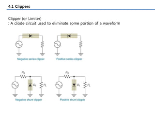
- 2. 4.1 Clippers Clipper (or Limiter) : A diode circuit used to eliminate some portion of a waveform
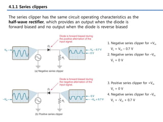
- 3. 4.1.1 Series clippers The series clipper has the same circuit operating characteristics as the half-wave rectifier, which provides an output when the diode is forward biased and no output when the diode is reverse biased 1. Negative series clipper for +Vin VL = Vin ŌĆō 0.7 V 2. Negative series clipper for ŌĆōVin VL = 0 V 3. Positive series clipper for +Vin VL = 0 V 4. Negative series clipper for ŌĆōVin VL = -Vin + 0.7 V
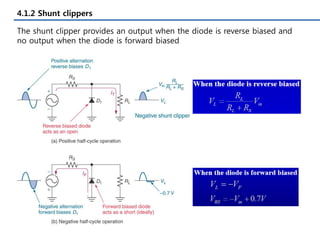
- 4. 4.1.2 Shunt clippers The shunt clipper provides an output when the diode is reverse biased and no output when the diode is forward biased
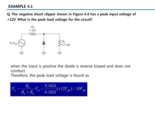
- 5. EXAMPLE 4.1 Q. The negative shunt clipper shown in Figure 4.4 has a peak input voltage of +12V. What is the peak load voltage for the circuit? when the input is positive the diode is reverse biased and does not conduct. Therefore, the peak load voltage is found as
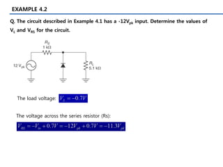
- 6. EXAMPLE 4.2 Q. The circuit described in Example 4.1 has a -12Vpk input. Determine the values of VL and VRS for the circuit. The load voltage: The voltage across the series resistor (Rs):
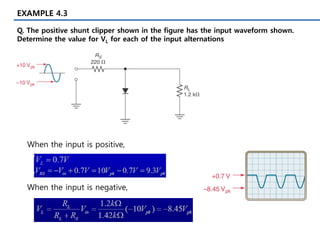
- 7. EXAMPLE 4.3 Q. The positive shunt clipper shown in the figure has the input waveform shown. Determine the value for VL for each of the input alternations When the input is positive, When the input is negative,
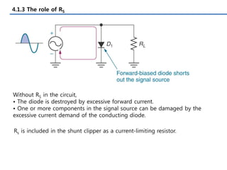
- 8. 4.1.3 The role of RS Without RS in the circuit, ŌĆó The diode is destroyed by excessive forward current. ŌĆó One or more components in the signal source can be damaged by the excessive current demand of the conducting diode. Rs is included in the shunt clipper as a current-limiting resistor.
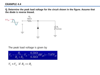
- 9. EXAMPLE 4.4 Q. Determine the peak load voltage for the circuit shown in the figure. Assume that the diode is reverse biased. The peak load voltage is given by if L in S L V V R R ’é╗ ’Ć╝’Ć╝
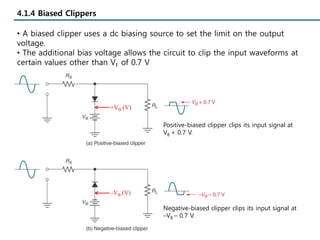
- 10. 4.1.4 Biased Clippers ŌĆó A biased clipper uses a dc biasing source to set the limit on the output voltage. ŌĆó The additional bias voltage allows the circuit to clip the input waveforms at certain values other than VF of 0.7 V +VB (V) -VB (V) Positive-biased clipper clips its input signal at VB + 0.7 V. Negative-biased clipper clips its input signal at ŌĆōVB ŌĆō 0.7 V.
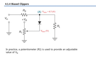
- 11. 4.1.4 Biased Clippers In practice, a potentiometer (R1) is used to provide an adjustable value of VB. VB,R1 (V) VB,R1 + 0.7 (V)
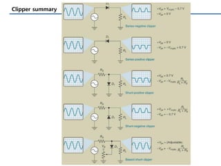
- 12. Clipper summary
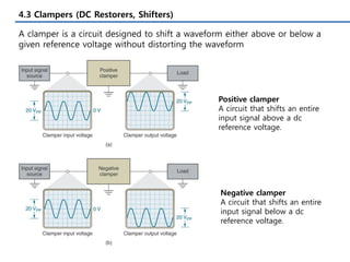
- 13. 4.3 Clampers (DC Restorers, Shifters) A clamper is a circuit designed to shift a waveform either above or below a given reference voltage without distorting the waveform Positive clamper A circuit that shifts an entire input signal above a dc reference voltage. Negative clamper A circuit that shifts an entire input signal below a dc reference voltage.
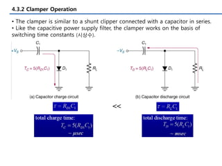
- 14. 4.3.2 Clamper Operation ŌĆó The clamper is similar to a shunt clipper connected with a capacitor in series. ŌĆó Like the capacitive power supply filter, the clamper works on the basis of switching time constants (ņŗ£ņāüņłś). <<
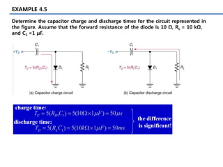
- 15. EXAMPLE 4.5 Determine the capacitor charge and discharge times for the circuit represented in the figure. Assume that the forward resistance of the diode is 10 ╬®, RL = 10 k╬®, and C1 =1 ╬╝F.
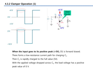
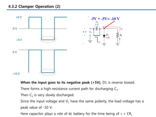
- 16. 4.3.2 Clamper Operation (1) When the input goes to its positive peak (+5V), D1 is forward biased. There forms a low-resistance current path for charging C1. Then C1 is rapidly charged to the full value (5V). With the applied voltage dropped across C1, the load voltage has a positive peak value of 0 V.
- 17. 4.3.2 Clamper Operation (2) When the input goes to its negative peak (+5V), D1 is reverse biased. There forms a high-resistance current path for discharging C1. Then C1 is very slowly discharged. Since the input voltage and VC have the same polarity, the load voltage has a peak value of -10 V. Here capacitor plays a role of dc battery for the time being of t = CRL
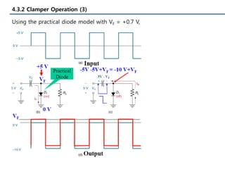
- 18. 4.3.2 Clamper Operation (3) Using the practical diode model with VF = +0.7 V,
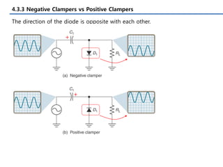
- 19. 4.3.3 Negative Clampers vs Positive Clampers The direction of the diode is opposite with each other. + +
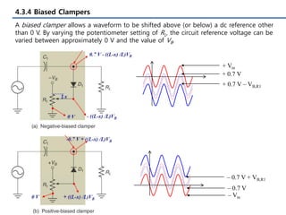
- 20. 4.3.4 Biased Clampers + Vin + 0.7 V + 0.7 V ŌĆō VB,R1 ŌĆō Vin ŌĆō 0.7 V ŌĆō 0.7 V + VB,R1 A biased clamper allows a waveform to be shifted above (or below) a dc reference other than 0 V. By varying the potentiometer setting of R1, the circuit reference voltage can be varied between approximately 0 V and the value of VB.
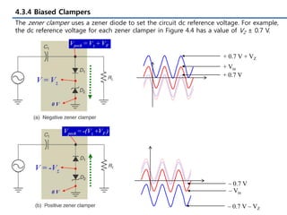
- 21. 4.3.4 Biased Clampers + Vin + 0.7 V + 0.7 V + VZ ŌĆō Vin ŌĆō 0.7 V ŌĆō 0.7 V ŌĆō VZ The zener clamper uses a zener diode to set the circuit dc reference voltage. For example, the dc reference voltage for each zener clamper in Figure 4.4 has a value of VZ ┬▒ 0.7 V.