Applications of power electronics in HVDC
•Download as PPTX, PDF•
5 likes•2,838 views

Role of Power electronics in HVDC and Transmission system. What are the components of Power electronics used in HVDC. Types of HVDC Links. Advantages of HVDC over HVAC.


Applications of power electronics in HVDC
- 1. APPLICATIONS OF POWER ELECTRONICS - HVDC 1
- 2. CONTENTS  Introduction  HVDC  Need for HVDC  Components of HVDC  Types of HVDC Links  Advantages  Disadvantages  Conclusion 2
- 3. INTRODUCTION  Power Electronics is the study of switching electronic circuits in order to control the flow of electrical energy.  It is literally impossible to list all the applications of power electronics today, as it has penetrated almost all the fields.  Some of the few are listed below,  Aerospace and Defense  Automotives and Traction  Home Appliances  Telecommunication  Utility System and Renewable energy 3
- 4. HVDC  A High Voltage Direct Current (HVDC) electric power transmission system uses direct current for the bulk transmission of electrical power, in contrast with the more common alternating current (AC) systems.  HVDC allows power transmission between unsynchronized AC transmission systems.  For long distance transmission, HVDC systems may be less expensive and suffer lower electrical losses.  An HVDC link can be controlled independently of the phase angle between source and load. 4
- 5. NEED FOR HVDC  As the load demand increases, for higher efficiency there must be only two possibilities,  To increase the generation  Minimize the losses  The losses which occur at all the stages in the system at generation, transmission and distribution level.  As the losses are greater in AC than DC, the losses can be greatly reduced by HVDC transmission.  Although there are certain in advantages of HVDC systems but also have the limitations. 5
- 6. COMPONENTS OF HVDC  Converters  Smoothing reactors  Harmonic filters  Reactive power supplies  Electrodes  DC Lines  AC Circuit breakers 6
- 7. COMPONENTS (Contd.,) 7  CONVERTERS: Perform AC to DC and DC to AC conversion. HVDC converters are usually built as 12-pulse circuits. Consists of valve bridges and transformer.  SMOOTHING REACTORS: Smoothing Reactors are serially connected reactors inserted in DC systems to reduce harmonic currents and transient over currents and/or current ripples in DC systems. Prevent commutation failure in inverter.
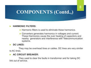
- 8. COMPONENTS (Contd.,)  HARMONIC FILTERS:  Harmonic filters is used to eliminate these harmonics.  Converters generates harmonics in voltages and current. These Harmonics cause the over heating of capacitors and nearby generators and interference with Telecommunication systems.  DC LINES: They may be overhead lines or cables. DC lines are very similar to AC lines.  AC CIRCUIT BREAKER: They used to clear the faults in transformer and for taking DC link out of service. 8
- 9. COMPONENTS (Contd.,)  REACTIVE POWER SUPPLIER: Under steady state condition, the reactive power consumed by the converter is about 50% of the active power transferred. Under transient conditions it could be much higher. For a strong AC power system, this reactive power is provided by a shunt capacitor.  ELECTRODES : Electrodes are conductors that provide connection to the earth for neutral and they have large surface to minimize current and surface voltage gradients. 9
- 10. TYPES OF HVDC LINKS  Monopolar links  Bipolar links  Homopolar link  Back to Back Links  Multi terminal links 10
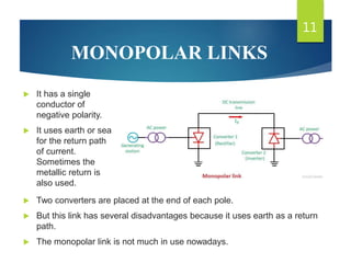
- 11. MONOPOLAR LINKS 11  It has a single conductor of negative polarity.  It uses earth or sea for the return path of current. Sometimes the metallic return is also used.  Two converters are placed at the end of each pole.  But this link has several disadvantages because it uses earth as a return path.  The monopolar link is not much in use nowadays.
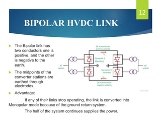
- 12. BIPOLAR HVDC LINK 12  The Bipolar link has two conductors one is positive, and the other is negative to the earth.  The midpoints of the converter stations are earthed through electrodes.  Advantage: If any of their links stop operating, the link is converted into Monopolar mode because of the ground return system. The half of the system continues supplies the power.
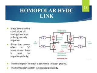
- 13. HOMOPOLAR HVDC LINK 13  It has two or more conductors all having the same polarity, usually negative  Since the corona effect in DC transmission lines is less for negative polarity.  The return path for such a system is through ground.  The homopolar system is not used presently.
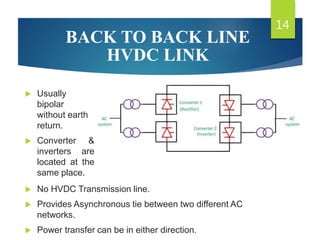
- 14. BACK TO BACK LINE HVDC LINK 14  Usually bipolar without earth return.  Converter & inverters are located at the same place.  No HVDC Transmission line.  Provides Asynchronous tie between two different AC networks.  Power transfer can be in either direction.
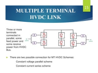
- 15. MULTIPLE TERMINAL HVDC LINK 15  There are two possible connection for MT HVDC Schemes: Constant voltage parallel scheme Constant current series scheme Three or more terminals connected in parallel, some feed power and some receive power from HVDC Bus.
- 16. ADVANTAGES  Loss is very less as no frequency reversals taken into account  Interconnection of asynchronously operated power Systems  Absence of transmission line limitations  Simple in construction  Fast change of energy flow i.e. Ability of quick and bidirectional control of energy flow  Lesser corona loss and radio interference  Greater reliability  Can be used for submarine and underground transmission  Low cost of DC lines, cables and Insulators and towers. 16
- 17. DISADVANTAGES 17  Use of converters ,filters etc increases the overall cost  Expensive inverters with limited overloading capacity  DC circuit breakers are more expensive  HVDC converters have low overloading capacity  More maintenance is required for insulators  Voltage transformation is possible only on AC side  Higher losses in the static inverter at smaller transmission
- 18. 18