
![DECLARING VARIABLES
’üČBoolean: boolean variableName;
’üČInteger: int variableName;
’üČCharacter: char variableName;
’üČString: stringName [ ];](https://image.slidesharecdn.com/arduinoabcd-240730135425-9fd49b44/85/Arduino-board-program-for-Mobile-robotss-38-320.jpg)


More Related Content
Similar to Arduino board program for Mobile robotss (20)
Recently uploaded (20)


Arduino board program for Mobile robotss
- 1. COIMBATORE ŌĆō 641 004 SESSION 1 PSG COLLEGE OF TECHNOLOGY 1 Selvaraj. K Project Engineer PSG-Robotics
- 2. OVERVIEW ’üČ Microcontroller Defined ’üČ Arduino Defined ’üČ Arduino Advantages ’üČ Arduino Applications ’üČ Types of Arduino Boards ’üČ Analog, Digital, Inputs and Outputs
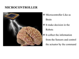
- 3. MICROCONTROLLER ’üČ Microcontroller Like as Brain ’üČ It make decision in the Robots ’üČ It collect the information from the Sensors and control the actuator by the command
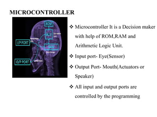
- 4. MICROCONTROLLER ’üČ Microcontroller It is a Decision maker with help of ROM,RAM and Arithmetic Logic Unit. ’üČ Input port- Eye(Sensor) ’üČ Output Port- Mouth(Actuators or Speaker) ’üČ All input and output ports are controlled by the programming
- 5. MICROCONTROLLER ’üČ Programmers work in the virtual world. ’üČ Machinery works in the physical world. ’üČ How does one connect the virtual world to the physical world? ’üČ A microcontroller is basically a small-scale computer with generalized (and programmable) inputs and outputs. ’üČ The inputs and outputs can be manipulated by and can manipulate the physical world
- 6. INTRODUCTION ABOUT ARDUINO ’üČBased on a simple micro-controller board, and ’üČA development environment (IDE) for writing software for the board ’üČOpen source electronics prototyping platform based on flexible ,Easy to use hardware and software ’üČArduino can be used to develop interactive objects, taking inputs from a variety of switches or sensors, and controlling a variety of lights, motors, and other physical outputs. Arduino projects can be stand-alone, or they can be communicate with software running on your computer (e.g. Flash, Processing, MaxMSP.) The boards can be assembled by hand or purchased preassembled; the open-source IDE can be downloaded for free. ’üČThe Arduino programming language is an implementation of Wiring, a similar physical computing platform, which is based on the Processing multimedia programming environment.
- 7. MAIN ADVANTAGES OF ARDUINO ’üČ Arduino microcontrollers have become the de facto standard. ’üČMake Magazine features many projects using Arduino microcontrollers. ’üČ Strives for the balance between ease of use and usefulness. ’üČProgramming languages seen as major obstacle. ’üČArduino C is a greatly simplified version of C++. ’üČ Unit price around Rs.1400
- 8. APPLICATION AREAS ’üČLight control ’üČMotor control ’üČAutomation ’üČRobotics ’üČNetworking ’üČCustom protocols ’üČYour imagination is the limitŌĆ”
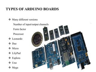
- 9. TYPES OF ARDUINO BOARDS ’üČ Many different versions Number of input/output channels Form factor Processor ’üČ Leonardo ’üČ Due ’üČ Micro ’üČ LilyPad ’üČ Esplora ’üČ Uno ’üČ Mega
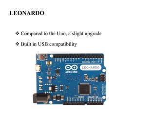
- 10. LEONARDO ’üČ Compared to the Uno, a slight upgrade ’üČ Built in USB compatibility
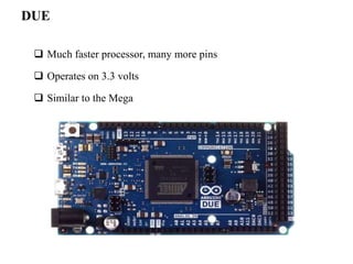
- 11. DUE ’ü▒ Much faster processor, many more pins ’ü▒ Operates on 3.3 volts ’ü▒ Similar to the Mega
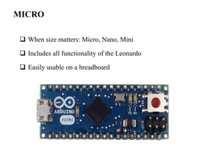
- 12. MICRO ’ü▒ When size matters: Micro, Nano, Mini ’ü▒ Includes all functionality of the Leonardo ’ü▒ Easily usable on a breadboard
- 13. LILYPAD ’üČ LilyPad is popular for clothing-based projects. ’üČ It is a Low weight and flexible
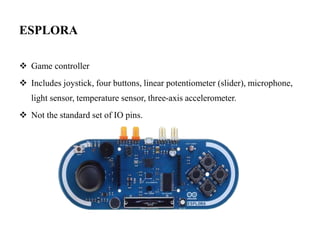
- 14. ESPLORA ’üČ Game controller ’üČ Includes joystick, four buttons, linear potentiometer (slider), microphone, light sensor, temperature sensor, three-axis accelerometer. ’üČ Not the standard set of IO pins.
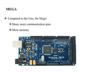
- 15. MEGA ’üČ Compared to the Uno, the Mega: ’üČMany more communication pins ’üČMore memory
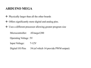
- 16. ARDUINO MEGA ’üČ Physically larger than all the other boards ’üČ Offers significantly more digital and analog pins. ’üČ Uses a different processor allowing greater program size Microcontroller: ATmega1280 Operating Voltage 5V Input Voltage: 7-12V Digital I/O Pins 54 (of which 14 provide PWM output)
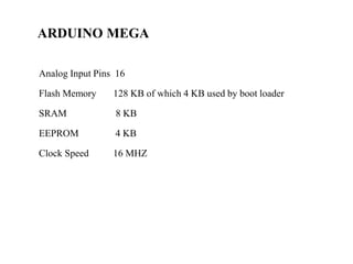
- 17. ARDUINO MEGA Analog Input Pins 16 Flash Memory 128 KB of which 4 KB used by boot loader SRAM 8 KB EEPROM 4 KB Clock Speed 16 MHZ
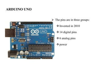
- 18. ARDUINO UNO ’āś The pins are in three groups: ’üČInvented in 2010 ’üČ14 digital pins ’üČ6 analog pins ’üČpower
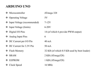
- 19. ARDUINO UNO ’üČ Microcontroller ATmega 328 ’üČ Operating Voltage 5V ’üČ Input Voltage (recommended) 7-12V ’üČ Input Voltage (limits) 6-20V ’üČ Digital I/O Pins 14 (of which 6 provide PWM output) ’üČ Analog Input Pins 6 ’üČ DC Current per I/O Pin 40 mA ’üČ DC Current for 3.3V Pin 50 mA ’üČ Flash Memory 32 KB (of which 0.5 KB used by boot loader) ’üČ SRAM 2 KB (ATmega328) ’üČ EEPROM 1 KB (ATmega328) ’üČ Clock Speed 16 MHz
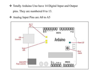
- 20. ’üČ Totally Arduino Uno have 14 Digital Input and Output pins. They are numbered 0 to 13. ’üČ Analog Input Pins are A0 to A5
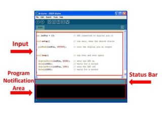
- 22. UNDERSTANDING INPUT VS OUTPUT ’üČ INPUT PIN Inputs is a signal / information going into the board. ’üČ OUTPUT PIN Output is any signal exiting the board.
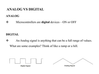
- 23. ANALOG VS DIGITAL ANALOG ’üČ Microcontrollers are digital devices ŌĆō ON or OFF DIGITAL ’üČ An Analog signal is anything that can be a full range of values. What are some examples? Think of like a ramp or a hill.
- 24. INPUT and OUTPUT 1. analogRead-Analog INPUT 2. analogWrite-Analog OUTPUT 3. digitalRead- digital INPUT 4. digitalWrite- digital OUTPUT
- 25. BASIC KNOWLEDGE REQUIRED ’é¦ Ohms LAW ’é¦ Current ’é¦ Voltage ’é¦ Resister ’é¦ Capacitor ’é¦ Inductor ’é¦ Voltage LAW ’é¦ Current Law ’é¦ Rheostat function ’é¦ Transformer ’é¦ Rectifier ’é¦ Regulator ’é¦ Inverter ’é¦ Amplifier ’é¦ Diode ’é¦ Transistor ’é¦ AC and DC Voltages ’é¦ Types of Motors ’é¦ Basic sensors
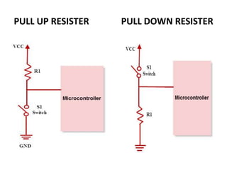
- 26. PULL UP RESISTER PULL DOWN RESISTER
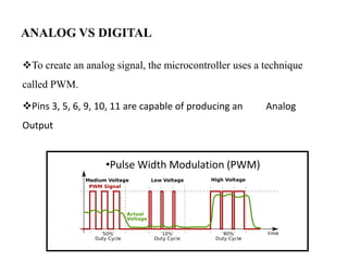
- 27. ANALOG VS DIGITAL ’üČTo create an analog signal, the microcontroller uses a technique called PWM. ’üČPins 3, 5, 6, 9, 10, 11 are capable of producing an Analog Output ŌĆóPulse Width Modulation (PWM)
- 28. SESSION II
- 29. OVERVIEW ’üČ Objectives ’üČ Startup Arduino IDE ’üČ Arduino Sketch Details ’üČ Commands ,Operators, Variables ’üČ Basic Repetitions ’üČ Settings and Configurations
- 30. OBJECTIVES ’üČ Provide a thorough introduction to the Arduino programming environment. ’üČ Develop a use of simple functions to interact with the LEDs, light sensor, push button, and buzzer on the Protosnap Pro Mini.
- 31. STARTUPARDUINO IDE ’üČ Double-click on either the Arduino Icon or wherever you installed (saved) the Arduino program.
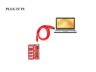
- 32. PLUG IT IN
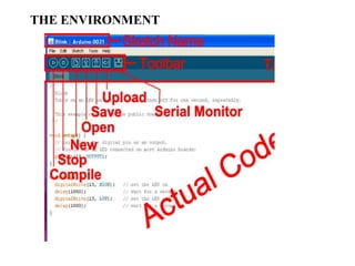
- 33. THE ENVIRONMENT
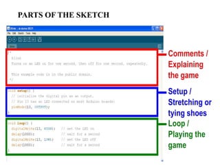
- 34. PARTS OF THE SKETCH
- 35. COMMENTS ’üČ Comments can be anywhere ’üČ Comments created with // or /* and */ ’üČ Comments do not affect code ’üČ You may not need comments, but think about the community.
- 36. OPERATORS The equals sign ’üČ= is used to assign a value ’üČ== is used to compare values ’üČAnd & Or ’üČ&& is ŌĆ£andŌĆØ ’üČ|| is ŌĆ£orŌĆØ
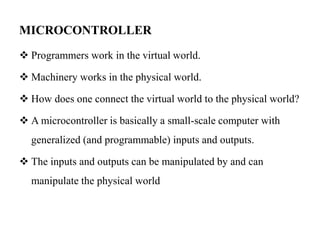
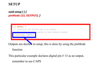
- 38. DECLARING VARIABLES ’üČBoolean: boolean variableName; ’üČInteger: int variableName; ’üČCharacter: char variableName; ’üČString: stringName [ ];
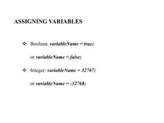
- 39. ASSIGNING VARIABLES ’üČ Boolean: variableName = true; or variableName = false; ’üČ Integer: variableName = 32767; or variableName = -32768;
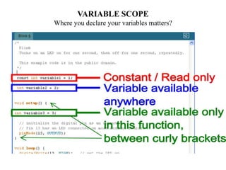
- 40. VARIABLE SCOPE Where you declare your variables matters?
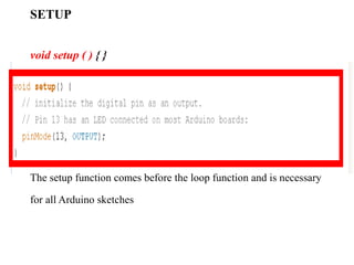
- 41. SETUP void setup ( ) { } The setup function comes before the loop function and is necessary for all Arduino sketches
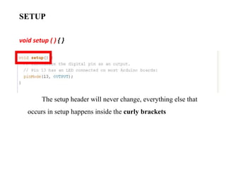
- 42. SETUP void setup ( ) { } The setup header will never change, everything else that occurs in setup happens inside the curly brackets
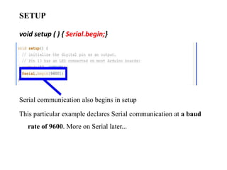
- 43. SETUP void setup ( ) { pinMode (13, OUTPUT); } Outputs are declare in setup, this is done by using the pinMode function This particular example declares digital pin # 13 as an output, remember to use CAPS
- 44. SETUP void setup ( ) { Serial.begin;} Serial communication also begins in setup This particular example declares Serial communication at a baud rate of 9600. More on Serial later...
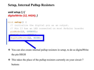
- 45. Setup, Internal Pullup Resistors void setup ( ) { digitalWrite (12, HIGH); } ’üČ You can also create internal pullup resistors in setup, to do so digitalWrite the pin HIGH ’üČ This takes the place of the pullup resistors currently on your circuit 7 buttons
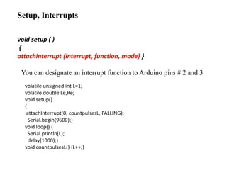
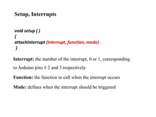
- 46. Setup, Interrupts void setup ( ) { attachInterrupt (interrupt, function, mode) } You can designate an interrupt function to Arduino pins # 2 and 3 volatile unsigned int L=1; volatile double Le,Re; void setup() { attachInterrupt(0, countpulsesL, FALLING); Serial.begin(9600);} void loop() { Serial.println(L); delay(1000);} void countpulsesL() {L++;}
- 47. Setup, Interrupts void setup ( ) { attachInterrupt (interrupt, function, mode) } Interrupt: the number of the interrupt, 0 or 1, corresponding to Arduino pins # 2 and 3 respectively Function: the function to call when the interrupt occurs Mode: defines when the interrupt should be triggered
- 48. Setup, Interrupts void setup ( ) { attachInterrupt (interrupt, function, mode) } ’üČLOW whenever pin state is low ’üČCHANGE whenever pin changes value ’üČRISING whenever pin goes from low to high ’üČFALLING whenever pin goes from low to high ’üČDonŌĆÖt forget to CAPITALIZE
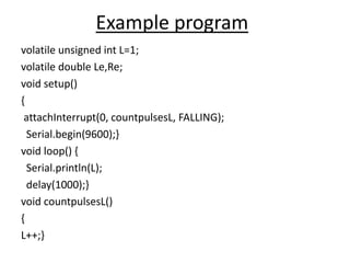
- 49. Example program volatile unsigned int L=1; volatile double Le,Re; void setup() { attachInterrupt(0, countpulsesL, FALLING); Serial.begin(9600);} void loop() { Serial.println(L); delay(1000);} void countpulsesL() { L++;}
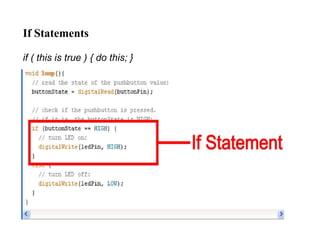
- 50. If Statements if ( this is true ) { do this; }
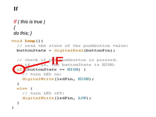
- 51. If If ( this is true ) { do this; }
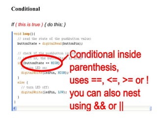
- 52. Conditional If ( this is true ) { do this; }
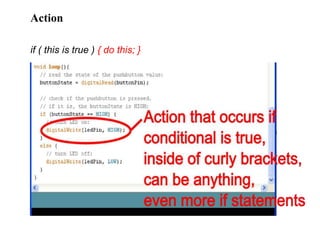
- 53. Action if ( this is true ) { do this; }
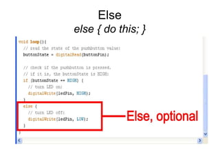
- 54. Else else { do this; }
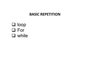
- 55. BASIC REPETITION ’ü▒ loop ’ü▒ For ’ü▒ while
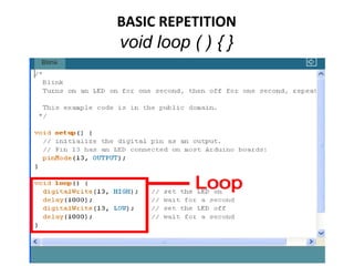
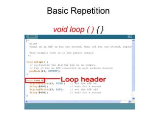
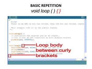
- 56. BASIC REPETITION void loop ( ) { }
- 57. Basic Repetition void loop ( ) { }
- 58. BASIC REPETITION void loop ( ) { }
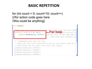
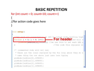
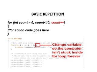
- 59. BASIC REPETITION for (int count = 0; count<10; count++) {//for action code goes here //this could be anything}
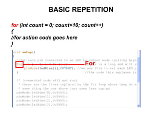
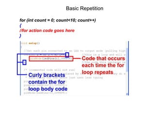
- 60. BASIC REPETITION for (int count = 0; count<10; count++) { //for action code goes here }
- 61. BASIC REPETITION for (int count = 0; count<10; count++) { //for action code goes here }
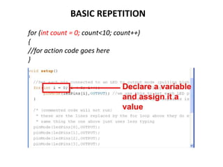
- 62. BASIC REPETITION for (int count = 0; count<10; count++) { //for action code goes here }
- 63. Basic Repetition for (int count = 0; count<10; count++) { //for action code goes here }
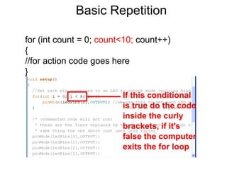
- 64. BASIC REPETITION for (int count = 0; count<10; count++) { //for action code goes here }
- 65. Basic Repetition for (int count = 0; count<10; count++) { //for action code goes here }
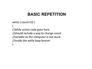
- 66. BASIC REPETITION while ( count<10 ) { //while action code goes here //should include a way to change count //variable so the computer is not stuck //inside the while loop forever }
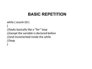
- 67. BASIC REPETITION while ( count<10 ) { //looks basically like a ŌĆ£forŌĆØ loop //except the variable is declared before //and incremented inside the while //loop }
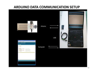
- 68. ARDUINO DATA COMMUNICATION SETUP 68
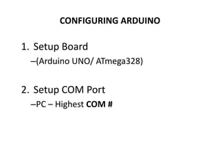
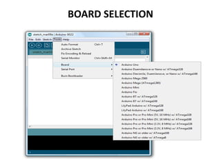
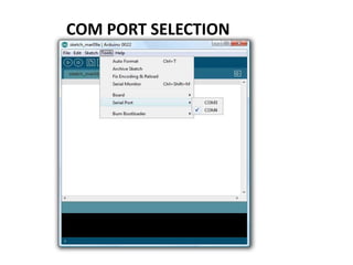
- 69. CONFIGURING ARDUINO 1. Setup Board ŌĆō(Arduino UNO/ ATmega328) 2. Setup COM Port ŌĆōPC ŌĆō Highest COM #
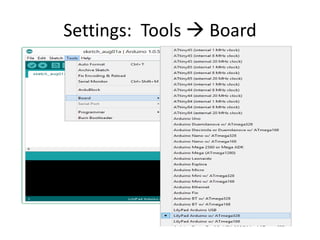
- 70. Settings: Tools ’āĀ Board
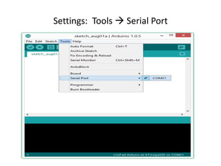
- 71. Settings: Tools ’āĀ Serial Port
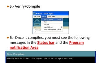
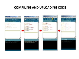
- 73. 5.- Verify/Compile 6.- Once it compiles, you must see the following messages in the Status bar and the Program notification Area
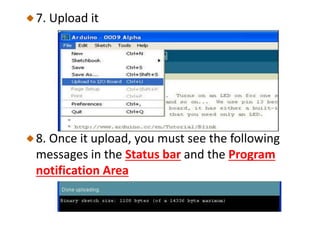
- 74. 7. Upload it 8. Once it upload, you must see the following messages in the Status bar and the Program notification Area
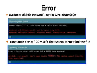
- 75. Error avrdude: stk500_getsync(): not in sync: resp=0x00 can't open device "COM10": The system cannot find the file specified
- 76. ARDUINO PROGRAMMING CHALLENGES Session III &IV
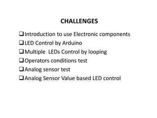
- 77. CHALLENGES ’ü▒Introduction to use Electronic components ’ü▒LED Control by Arduino ’ü▒Multiple LEDs Control by looping ’ü▒Operators conditions test ’ü▒Analog sensor test ’ü▒Analog Sensor Value based LED control
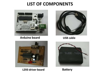
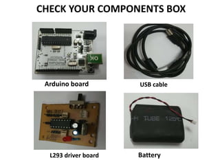
- 78. LIST OF COMPONENTS Arduino board USB cable L293 driver board Battery
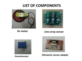
- 79. LIST OF COMPONENTS Dc motor Line array sensor Potentiometer Ultrasonic sensor adapter
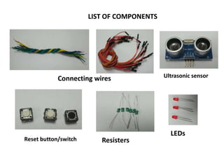
- 80. LIST OF COMPONENTS Connecting wires Ultrasonic sensor LEDs Resisters Reset button/switch
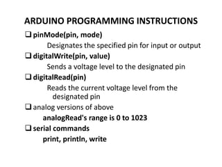
- 81. ARDUINO PROGRAMMING INSTRUCTIONS ’ü▒pinMode(pin, mode) Designates the specified pin for input or output ’ü▒digitalWrite(pin, value) Sends a voltage level to the designated pin ’ü▒digitalRead(pin) Reads the current voltage level from the designated pin ’ü▒analog versions of above analogRead's range is 0 to 1023 ’ü▒serial commands print, println, write
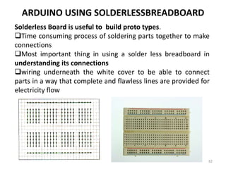
- 82. ARDUINO USING SOLDERLESSBREADBOARD Solderless Board is useful to build proto types. ’ü▒Time consuming process of soldering parts together to make connections ’ü▒Most important thing in using a solder less breadboard in understanding its connections ’ü▒wiring underneath the white cover to be able to connect parts in a way that complete and flawless lines are provided for electricity flow 82
- 83. Instruction to Components handling 1. Doing circuit connection ŌĆō DonŌĆÖt power up Controller board 2. DonŌĆÖt use metal surface and maintain at free surface 3. Circuit check before power up 4. DonŌĆÖt make short circuit 5. After completion of Experiments- all components put in to box and cross check the list
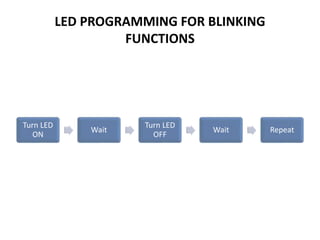
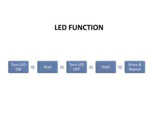
- 84. LED PROGRAMMING FOR BLINKING FUNCTIONS Turn LED ON Wait Turn LED OFF Wait Repeat
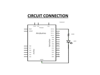
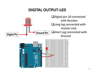
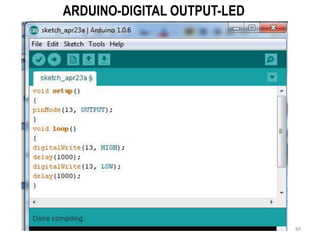
- 86. DIGITAL OUTPUT-LED 86 ’ü▒Digital pin 10 connected with Resister. ’ü▒Long leg connected with resister end. ’ü▒short Leg connected with Ground. Ground Pin Digital Pin
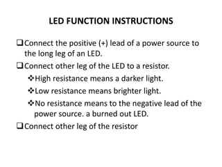
- 87. LED FUNCTION INSTRUCTIONS ’ü▒Connect the positive (+) lead of a power source to the long leg of an LED. ’ü▒Connect other leg of the LED to a resistor. ’üČHigh resistance means a darker light. ’üČLow resistance means brighter light. ’üČNo resistance means to the negative lead of the power source. a burned out LED. ’ü▒Connect other leg of the resistor
- 88. LED FUNCTION Turn LED ON Wait Turn LED OFF Wait Rinse & Repeat
- 90. BOARD SELECTION
- 92. COMPILING AND UPLOADING CODE
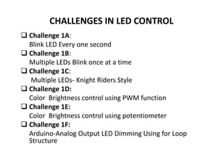
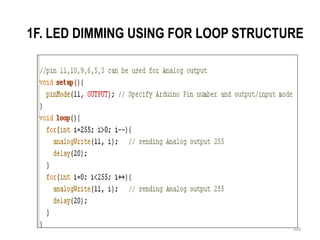
- 93. CHALLENGES IN LED CONTROL ’ü▒ Challenge 1A: Blink LED Every one second ’ü▒ Challenge 1B: Multiple LEDs Blink once at a time ’ü▒ Challenge 1C: Multiple LEDs- Knight Riders Style ’ü▒ Challenge 1D: Color Brightness control using PWM function ’ü▒ Challenge 1E: Color Brightness control using potentiometer ’ü▒ Challenge 1F: Arduino-Analog Output LED Dimming Using for Loop Structure
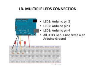
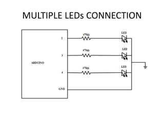
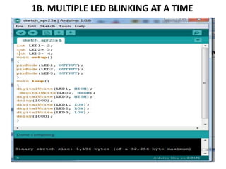
- 94. 1B. MULTIPLE LEDS CONNECTION ŌĆó LED1: Arduino pin2 ŌĆó LED2: Arduino pin3 ŌĆó LED3: Arduino pin4 ŌĆó All LEDŌĆÖs Gnd- Connected with Arduino Ground
- 96. 1B. MULTIPLE LED BLINKING AT A TIME
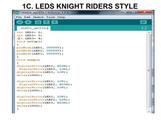
- 97. 1C. LEDS KNIGHT RIDERS STYLE
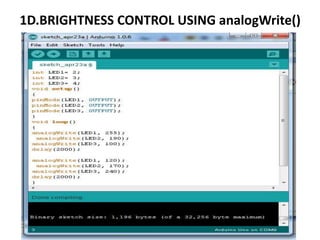
- 98. 1D.BRIGHTNESS CONTROL USING analogWrite()
- 99. 1E.Color Brightness control using potentiometer
- 100. 1F. LED DIMMING USING FOR LOOP STRUCTURE 100
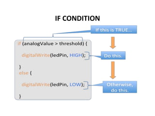
- 102. IF CONDITION
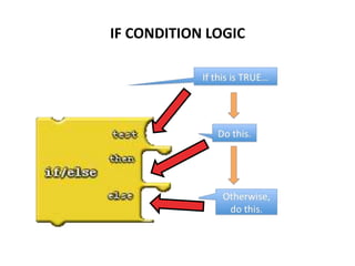
- 103. IF CONDITION LOGIC
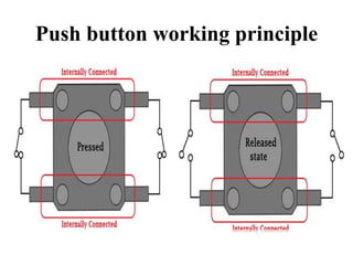
- 104. Push button working principle
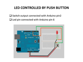
- 105. LED CONTROLLED BY PUSH BUTTON ’ü▒ Switch output connected with Arduino pin2 ’ü▒ Led pin connected with Arduino pin 6
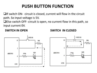
- 106. PUSH BUTTON FUNCTION SWITCH IN OPEN SWITCH IN CLOSED ’ü▒If switch ON- circuit is closed, current will flow in the circuit path. So input voltage is 5V. ’ü▒Else switch OFF- circuit is open, no current flow in this path, so input current 0V.
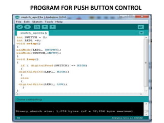
- 107. PROGRAM FOR PUSH BUTTON CONTROL
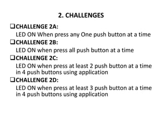
- 108. 2. CHALLENGES ’ü▒CHALLENGE 2A: LED ON When press any One push button at a time ’ü▒CHALLENGE 2B: LED ON when press all push button at a time ’ü▒CHALLENGE 2C: LED ON when press at least 2 push button at a time in 4 push buttons using application ’ü▒CHALLENGE 2D: LED ON when press at least 3 push button at a time in 4 push buttons using application
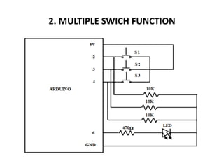
- 109. 2. MULTIPLE SWICH FUNCTION
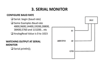
- 110. 3. SERIAL MONITOR CONFIGURE BAUD RATE ’ü▒ Serial. begin (baud rate) ’ü▒ Some Examples Baud rate 4800,9600,14400,19200,28800, 38400,5760 and 115200ŌĆ” etc ’ü▒ AnalogRead Value is 0 to 1023 WATCHING OUTPUT AT SERIAL MONITOR ’ü▒ Serial.println();
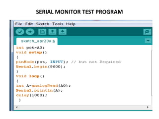
- 111. SERIAL MONITOR TEST PROGRAM
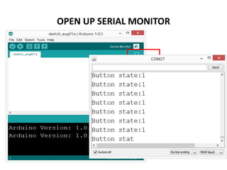
- 112. OPEN UP SERIAL MONITOR
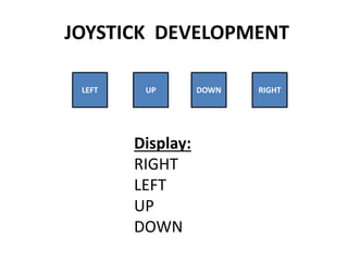
- 113. JOYSTICK DEVELOPMENT LEFT UP DOWN RIGHT Display: RIGHT LEFT UP DOWN
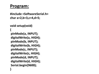
- 114. Program: #include <SoftwareSerial.h> char a=2,b=3,c=4,d=5; void setup(void) { pinMode(a, INPUT); digitalWrite(a, HIGH); pinMode(b, INPUT); digitalWrite(b, HIGH); pinMode(c, INPUT); digitalWrite(c, HIGH); pinMode(d, INPUT); digitalWrite(d, HIGH); Serial.begin(9600); }
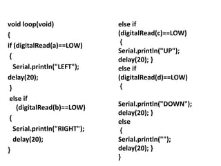
- 115. void loop(void) { if (digitalRead(a)==LOW) { Serial.println("LEFT"); delay(20); } else if (digitalRead(b)==LOW) { Serial.println("RIGHT"); delay(20); } else if (digitalRead(c)==LOW) { Serial.println("UP"); delay(20); } else if (digitalRead(d)==LOW) { Serial.println("DOWN"); delay(20); } else { Serial.println(""); delay(20); } }
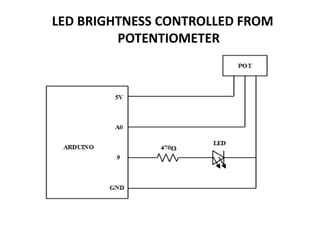
- 116. LED BRIGHTNESS CONTROLLED FROM POTENTIOMETER
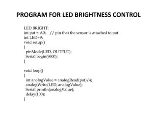
- 117. PROGRAM FOR LED BRIGHTNESS CONTROL LED BRIGHT: int pot = A0; // pin that the sensor is attached to pot int LED=9; void setup() { pinMode(LED, OUTPUT); Serial.begin(9600); } void loop() { int analogValue = analogRead(pot)/4; analogWrite(LED, analogValue); Serial.println(analogValue); delay(100); }
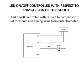
- 118. LED ON/OFF CONTROLLED WITH RESPECT TO COMPARISON OF THRESHOLD Led on/off controlled with respect to comparison of threshold and analog value from potentiometer
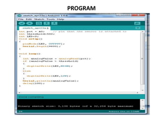
- 119. PROGRAM
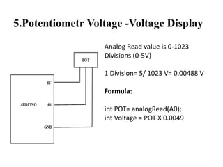
- 120. 5.Potentiometr Voltage -Voltage Display Analog Read value is 0-1023 Divisions (0-5V) 1 Division= 5/ 1023 V= 0.00488 V Formula: int POT= analogRead(A0); int Voltage = POT X 0.0049
- 121. HOME MADE AUTOMATION ’ü▒ If push button is pressed at once- Automatically electrical fans and lights will ON ’ü▒If again press the same push button Automatically electrical fans and lights will OFF Experiments: LED will ON/ OFF based on this condition
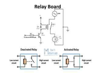
- 122. Relay Board
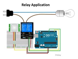
- 123. Relay Application
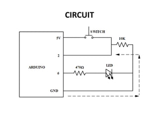
- 124. CIRCUIT
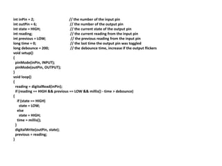
- 125. int inPin = 2; // the number of the input pin int outPin = 6; // the number of the output pin int state = HIGH; // the current state of the output pin int reading; // the current reading from the input pin int previous = LOW; // the previous reading from the input pin long time = 0; // the last time the output pin was toggled long debounce = 200; // the debounce time, increase if the output flickers void setup() { pinMode(inPin, INPUT); pinMode(outPin, OUTPUT); } void loop() { reading = digitalRead(inPin); if (reading == HIGH && previous == LOW && millis() - time > debounce) { if (state == HIGH) state = LOW; else state = HIGH; time = millis(); } digitalWrite(outPin, state); previous = reading; }
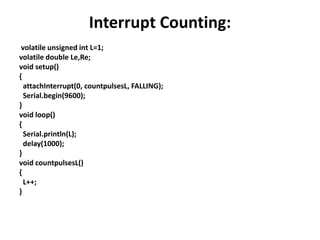
- 126. Interrupt Counting: volatile unsigned int L=1; volatile double Le,Re; void setup() { attachInterrupt(0, countpulsesL, FALLING); Serial.begin(9600); } void loop() { Serial.println(L); delay(1000); } void countpulsesL() { L++; }
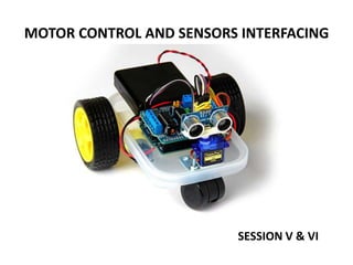
- 127. MOTOR CONTROL AND SENSORS INTERFACING SESSION V & VI
- 128. OVERVIEW ’ü▒Introduction about Sensors ’ü▒Introduction about Motors ’ü▒Motor control ’ü▒Ultrasonic Sensor Testing ’ü▒IR array sensor Testing ’ü▒Motor speed control based on Sensors value
- 129. INTRODUCTION ABOUT SENSORS ’ü▒ Sensor ’ü▒ Types of sensors IR sensor Sound sensor Temperature sensor ’ü▒ How to use it? ’ü▒ Where to use it?
- 130. WHAT IS A SENSORŌĆ”.? A sensor is a device that measures a physical quantity and converts it into a signal which can be read by an observer or by an instrument ’üĮ Sensors are used in everyday objects such as touch-sensitive elevator buttons (tactile sensor) and lamps which dim or brighten by touching the base ’üĮ Applications include cars, machines, aerospace, medicine, manufacturing and robotics
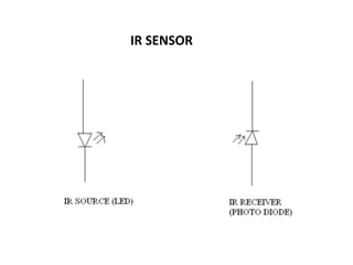
- 131. IR SENSOR
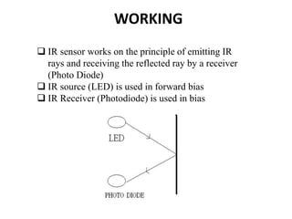
- 132. WORKING ’ü▒ IR sensor works on the principle of emitting IR rays and receiving the reflected ray by a receiver (Photo Diode) ’ü▒ IR source (LED) is used in forward bias ’ü▒ IR Receiver (Photodiode) is used in bias
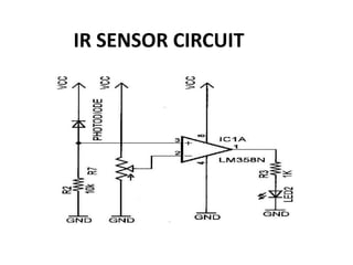
- 133. IR SENSOR CIRCUIT
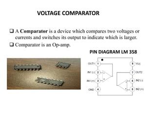
- 134. VOLTAGE COMPARATOR ’ü▒ A Comparator is a device which compares two voltages or currents and switches its output to indicate which is larger. ’ü▒ Comparator is an Op-amp. PIN DIAGRAM LM 358
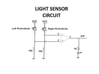
- 135. LIGHT SENSOR CIRCUIT
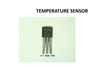
- 136. TEMPERATURE SENSOR
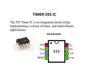
- 137. TIMER 555 IC The 555 Timer IC is an integrated circuit (chip) implementing a variety of timer and multivibrator applications. PIN DIAGRAM
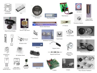
- 138. Solar Cell Digital Infrared Ranging Compass Touch Switch Pressure Switch Limit Switch Magnetic Reed Switch Magnetic Sensor Miniature Polaroid Sensor Polaroid Sensor Board Piezo Ultrasonic Transducers Pyroelectric Detector Thyristor Gas Sensor Gieger-Muller Radiation Sensor Piezo Bend Sensor Resistive Bend Sensors Mechanical Tilt Sensors Pendulum Resistive Tilt Sensors CDS Cell Resistive Light Sensor Hall Effect Magnetic Field Sensors Compass IRDA Transceiver IR Amplifier Sensor IR Modulator Receiver Lite-On IR Remote Receiver Radio Shack Remote Receiver IR Sensor w/lens Gyro Accelerometer IR Reflection Sensor IR Pin Diode UV Detector Metal Detector
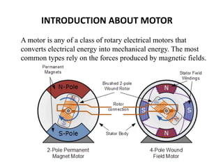
- 139. A motor is any of a class of rotary electrical motors that converts electrical energy into mechanical energy. The most common types rely on the forces produced by magnetic fields. INTRODUCTION ABOUT MOTOR
- 140. 16/11/2021 PSG College of Technology TYPES OF MOTORS ŌĆó AC motors ŌĆó DC motors ŌĆó DC geared motors ŌĆó Stepper motors ŌĆó Servo motors
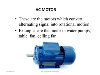
- 141. 16/11/2021 PSG College of Technology AC MOTOR ŌĆó These are the motors which convert alternating signal into rotational motion. ŌĆó Examples are the motor in water pumps, table fan, ceiling fan.
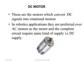
- 142. 16/11/2021 PSG College of Technology DC MOTOR ŌĆó These are the motors which convert DC signals into rotational motion ŌĆó In robotics applications they are preferred over AC motors as the motor and the complete circuit require same kind of supply i.e DC supply
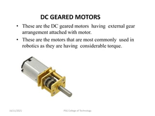
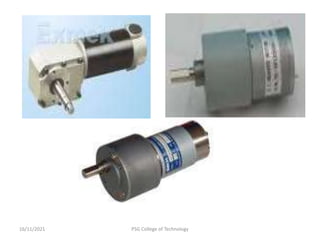
- 143. 16/11/2021 PSG College of Technology DC GEARED MOTORS ŌĆó These are the DC geared motors having external gear arrangement attached with motor. ŌĆó These are the motors that are most commonly used in robotics as they are having considerable torque.
- 144. 16/11/2021 PSG College of Technology
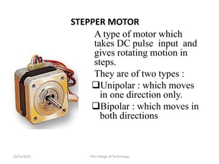
- 145. 16/11/2021 PSG College of Technology STEPPER MOTOR A type of motor which takes DC pulse input and gives rotating motion in steps. They are of two types : ’ü▒Unipolar : which moves in one direction only. ’ü▒Bipolar : which moves in both directions
- 147. 16/11/2021 PSG College of Technology
- 148. 16/11/2021 PSG College of Technology ŌĆó Servo motors are the most powerful motors for robotic applications. ŌĆó They comes in both variants , AC and DC. ŌĆó They can change the direction with same supply.
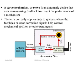
- 149. 16/11/2021 PSG College of Technology ŌĆó A servomechanism, or servo is an automatic device that uses error-sensing feedback to correct the performance of a mechanism ŌĆó The term correctly applies only to systems where the feedback or error-correction signals help control mechanical position or other parameters
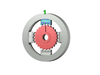
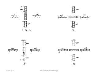
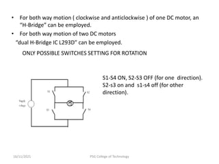
- 150. ŌĆó For both way motion ( clockwise and anticlockwise ) of one DC motor, an ŌĆ£H-BridgeŌĆØ can be employed. ŌĆó For both way motion of two DC motors ŌĆ£dual H-Bridge IC L293DŌĆØ can be employed. 16/11/2021 PSG College of Technology S1-S4 ON, S2-S3 OFF (for one direction). S2-s3 on and s1-s4 off (for other direction). ONLY POSSIBLE SWITCHES SETTING FOR ROTATION
- 151. 16/11/2021 PSG College of Technology
- 152. 16/11/2021 PSG College of Technology
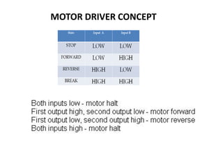
- 153. MOTOR DRIVER CONCEPT
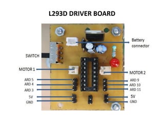
- 154. L293D DRIVER BOARD
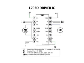
- 155. L293D DRIVER IC
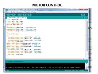
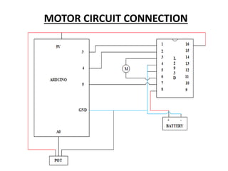
- 156. MOTOR CONTROL
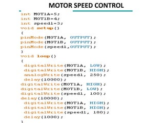
- 157. MOTOR SPEED CONTROL
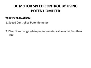
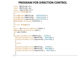
- 158. DC MOTOR SPEED CONTROL BY USING POTENTIOMETER TASK EXPLANATION: 1. Speed Control by Potentiometer 2. Direction change when potentiometer value move less than 500
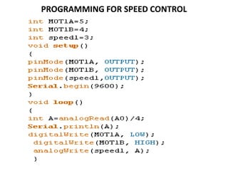
- 160. PROGRAMMING FOR SPEED CONTROL
- 161. PROGRAM FOR DIRECTION CONTROL
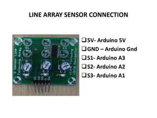
- 162. LINE ARRAY SENSOR CONNECTION ’ü▒5V- Arduino 5V ’ü▒GND ŌĆō Arduino Gnd ’ü▒S1- Arduino A3 ’ü▒S2- Arduino A2 ’ü▒S3- Arduino A1
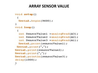
- 163. ARRAY SENSOR VALUE
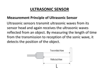
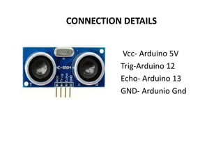
- 164. ULTRASONIC SENSOR Measurement Principle of Ultrasonic Sensor Ultrasonic sensors transmit ultrasonic waves from its sensor head and again receives the ultrasonic waves reflected from an object. By measuring the length of time from the transmission to reception of the sonic wave, it detects the position of the object.
- 165. CONNECTION DETAILS Vcc- Arduino 5V Trig-Arduino 12 Echo- Arduino 13 GND- Ardunio Gnd
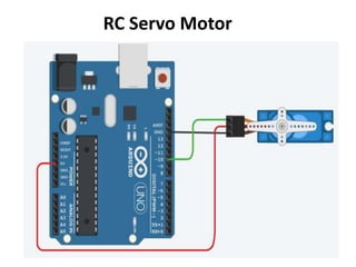
- 167. RC Servo Motor
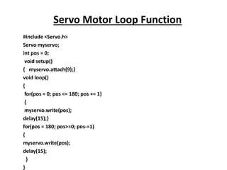
- 168. #include <Servo.h> Servo myservo; int pos = 0; void setup() { myservo.attach(9);} void loop() { for(pos = 0; pos <= 180; pos += 1) { myservo.write(pos); delay(15);} for(pos = 180; pos>=0; pos-=1) { myservo.write(pos); delay(15); } } Servo Motor Loop Function
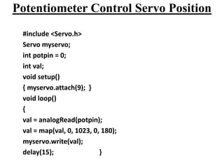
- 169. Potentiometer Control Servo Position #include <Servo.h> Servo myservo; int potpin = 0; int val; void setup() { myservo.attach(9); } void loop() { val = analogRead(potpin); val = map(val, 0, 1023, 0, 180); myservo.write(val); delay(15); }
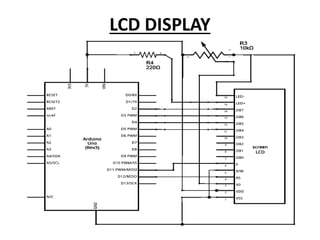
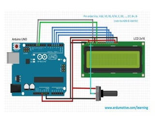
- 170. LCD DISPLAY
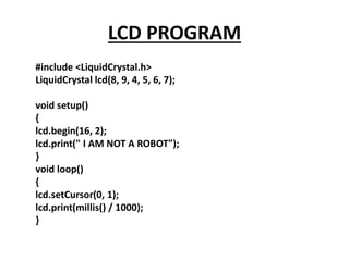
- 172. LCD PROGRAM #include <LiquidCrystal.h> LiquidCrystal lcd(8, 9, 4, 5, 6, 7); void setup() { lcd.begin(16, 2); lcd.print(" I AM NOT A ROBOT"); } void loop() { lcd.setCursor(0, 1); lcd.print(millis() / 1000); }
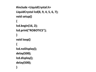
- 173. #include <LiquidCrystal.h> LiquidCrystal lcd(8, 9, 4, 5, 6, 7); void setup() { lcd.begin(16, 2); lcd.print(ŌĆ£ROBOTICS"); } void loop() { lcd.noDisplay(); delay(500); lcd.display(); delay(500); }
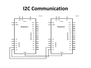
- 174. I2C Communication
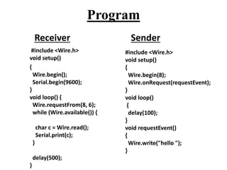
- 175. Program #include <Wire.h> void setup() { Wire.begin(); Serial.begin(9600); } void loop() { Wire.requestFrom(8, 6); while (Wire.available()) { char c = Wire.read(); Serial.print(c); } delay(500); } #include <Wire.h> void setup() { Wire.begin(8); Wire.onRequest(requestEvent); } void loop() { delay(100); } void requestEvent() { Wire.write("hello "); } Receiver Sender
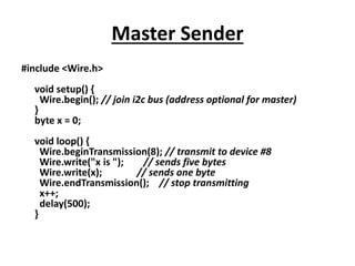
- 176. Master Sender #include <Wire.h> void setup() { Wire.begin(); // join i2c bus (address optional for master) } byte x = 0; void loop() { Wire.beginTransmission(8); // transmit to device #8 Wire.write("x is "); // sends five bytes Wire.write(x); // sends one byte Wire.endTransmission(); // stop transmitting x++; delay(500); }
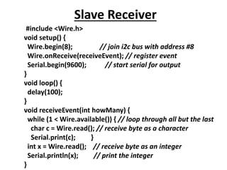
- 177. Slave Receiver #include <Wire.h> void setup() { Wire.begin(8); // join i2c bus with address #8 Wire.onReceive(receiveEvent); // register event Serial.begin(9600); // start serial for output } void loop() { delay(100); } void receiveEvent(int howMany) { while (1 < Wire.available()) { // loop through all but the last char c = Wire.read(); // receive byte as a character Serial.print(c); } int x = Wire.read(); // receive byte as an integer Serial.println(x); // print the integer }
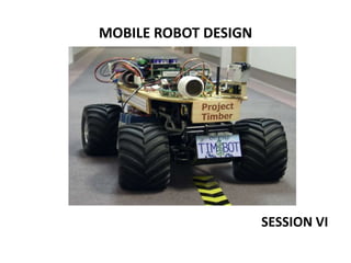
- 179. MOBILE ROBOT DESIGN SESSION VI
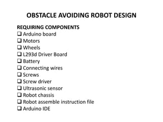
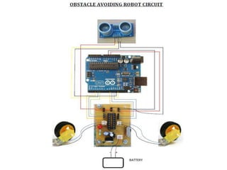
- 180. OBSTACLE AVOIDING ROBOT DESIGN REQUIRING COMPONENTS ’ü▒ Arduino board ’ü▒ Motors ’ü▒ Wheels ’ü▒ L293d Driver Board ’ü▒ Battery ’ü▒ Connecting wires ’ü▒ Screws ’ü▒ Screw driver ’ü▒ Ultrasonic sensor ’ü▒ Robot chassis ’ü▒ Robot assemble instruction file ’ü▒ Arduino IDE
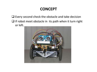
- 181. CONCEPT ’ü▒ Every second check the obstacle and take decision ’ü▒ If robot meet obstacle in its path when it turn right or left.
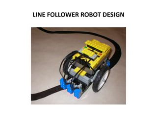
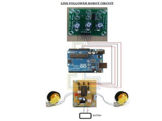
- 183. LINE FOLLOWER ROBOT DESIGN
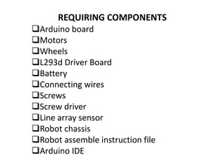
- 184. REQUIRING COMPONENTS ’ü▒Arduino board ’ü▒Motors ’ü▒Wheels ’ü▒L293d Driver Board ’ü▒Battery ’ü▒Connecting wires ’ü▒Screws ’ü▒Screw driver ’ü▒Line array sensor ’ü▒Robot chassis ’ü▒Robot assemble instruction file ’ü▒Arduino IDE
- 187. CHECK YOUR COMPONENTS BOX Arduino board USB cable L293 driver board Battery
- 188. LIST OF COMPONENTS Dc motor Line array sensor Potentiometer Ultrasonic sensor adapter
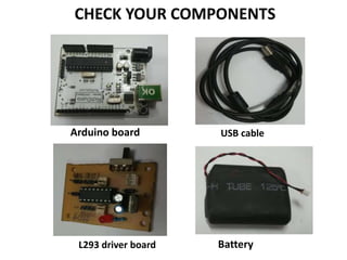
- 189. CHECK YOUR COMPONENTS Arduino board USB cable L293 driver board Battery
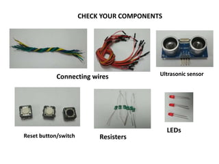
- 190. CHECK YOUR COMPONENTS Connecting wires Ultrasonic sensor LEDs Resisters Reset button/switch
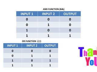
- 191. AND FUNCTION (&&) INPUT 1 INPUT 2 OUTPUT 0 0 0 0 1 0 1 0 0 1 1 1 INPUT 1 INPUT 2 OUTPUT 0 0 0 0 1 1 1 0 1 1 1 1 OR FUNCTION (||)