- Boolean algebra uses binary numbers (0 and 1) and logical operations (AND, OR, NOT) to analyze and simplify digital circuits.
- It was invented by George Boole in 1854 and represents variables that can be either 1 or 0.
- The document discusses Boolean operations, laws, logic gates, minimization techniques, and representing functions as sums of products.
Digital logic circuits can be classified as either combinational or sequential logic circuits. Combinational logic circuits have outputs that go low or high depending on the specific combination of input signals, regardless of the order in which inputs are applied. Digital circuits can also be programmable, where the functionality can be changed through software instead of changing the physical circuit.
Boolean algebra deals with logical operations on binary variables that have true or false values. It was first introduced by mathematician George Boole in 1854. Boolean algebra uses logical operators like AND, OR, and NOT, rather than numerical operations. Boolean functions and truth tables are used to represent logical relationships between binary variables. Key concepts in Boolean algebra include commutative, associative, distributive, inversion, and De Morgan's laws.
Boolean Aljabra.pptx of dld and computeritxminahil29
油
_Happiest birthday patner_"ズわき
Many many happy returns of the day わ.... may this year brings more happiness and success for u..... may uh have many more グ.... may urhh life be as beautiful as you are ..... may ur all desire wishes come true ..... May uh get double of everything uh want in ur life ......you're such a great guy and puri hearted and sweetest girl ス稲嶧....uh deserve all cakes hug an happiness today グ... hmesha khush rho pyariiiip....
Once again happy birthday My Gurl コわ
_JUG JUG JIYOOO__Happiest birthday patner_"ズわき
Many many happy returns of the day わ.... may this year brings more happiness and success for u..... may uh have many more グ.... may urhh life be as beautiful as you are ..... may ur all desire wishes come true ..... May uh get double of everything uh want in ur life ......you're such a great guy and puri hearted and sweetest girl ス稲嶧....uh deserve all cakes hug an happiness today グ... hmesha khush rho pyariiiip....
Once again happy birthday My Gurl コわ_Happiest birthday patner_"ズわき
Many many happy returns of the day わ.... may this year brings more happiness and success for u..... may uh have many more グ.... may urhh life be as beautiful as you are ..... may ur all desire wishes come true ..... May uh get double of everything uh want in ur life ......you're such a great guy and puri hearted and sweetest girl ス稲嶧....uh deserve all cakes hug an happiness today グ... hmesha khush rho pyariiiip....
Once again happy birthday My Gurl コわ
_JUG JUG JIYOOO_
_JUG JUG JIYOOO_
This document provides an overview of Boolean algebra and logic gates. It discusses basic logic gates like AND, OR, and NOT. It also covers other logic operations like NAND, NOR, EXOR and EXNOR. The document defines Boolean algebra and its postulates. It explains logic levels, positive and negative logic. It also discusses simplification of Boolean expressions, canonical and standard forms, and the use of Venn diagrams and minterms. The key topics covered are the basic concepts of Boolean algebra and digital logic that form the foundation for working with logic gates and circuits.
- Boolean algebra is a branch of algebra that represents logical relationships using the values true and false, represented by 1 and 0.
- It uses logical operations like AND, OR, and NOT to analyze and simplify digital circuits.
- Boolean algebra is based on laws like commutative, associative, and distributive laws, as well as De Morgan's laws, and is widely used in computer science and engineering.
This document discusses Boolean algebra and its fundamental concepts. It introduces Boolean algebra, which was developed by George Boole to express logical reasoning mathematically. Boolean algebra uses two values (1 and 0) and two operations (addition and multiplication). Addition represents logical OR, while multiplication represents logical AND. Logic gates like OR gates and AND gates perform Boolean operations. The document also covers de Morgan's theorems, duality, and proofs of several rules of Boolean algebra.
George Boole developed Boolean algebra in 1854 to simplify and analyze complex logical expressions using binary logic. Boolean algebra uses logical symbols like 0 and 1 to represent digital circuit inputs and outputs, and laws and rules to reduce complex expressions to equivalent simpler forms using fewer logic gates. Some key laws and rules include the commutative, associative, distributive, absorption, and De Morgan's laws. Boolean functions describe logical relationships between variables and can be represented by algebraic expressions or truth tables. Methods like Karnaugh maps are used to minimize expressions.
- Boolean logic is the mathematical system underlying digital circuits and logic gates. It represents binary states as true/false or 1/0.
- George Boole first developed a symbolic system of logic in 1854 known as Boolean algebra. Claude Shannon later applied it to electrical circuits.
- Digital logic gates like AND, OR, NOT implement Boolean logic and operate on binary inputs to produce binary outputs. More complex gates like NAND and NOR can be used to build any digital circuit.
- Boolean algebra uses postulates, theorems and truth tables to analyze and simplify digital logic circuits. Principles like duality, distribution and DeMorgan's laws allow simplifying expressions.
The document discusses different digital logic components including logic gates, flip flops, registers, and counters. It describes the basic types of logic gates such as AND, OR, NOT, NAND, and NOR gates. It also discusses different types of flip flops including T, S-R, J-K, and D flip flops which are used to store binary data. Registers are formed using groups of flip flops to store multi-bit data. Counters are also discussed as another component of digital logic systems.
The document discusses computer organization and architecture. It provides details about logic gates, which are the basic building blocks of digital circuits. The seven basic logic gates are AND, OR, XOR, NOT, NAND, NOR and XNOR. Boolean algebra is used to analyze and simplify digital circuits. Karnaugh maps are a graphical technique to simplify Boolean expressions and minimize the number of variables. They allow grouping of variables to obtain the simplified sum of products or product of sums form.
This document provides an overview of Boolean algebra. It begins by discussing how George Boole developed a system of logic and algebra (Boolean algebra) to represent logical statements and operations. Next, it defines binary valued variables that can only take on true or false values. It then explains how logical statements are combined using logical operators like AND, OR, and NOT. Truth tables are introduced as a way to represent all possible combinations and outputs of logical statements. Common logic gates like AND, OR, and NOT gates are described along with their truth tables. The document concludes with a brief mention of basic postulates and theorems of Boolean algebra.
This document discusses Boolean algebra and logic gates. It defines Boolean algebra as having two values - True or False. Logic circuits in computers are also designed to have two states - high (1) or low (0). The three basic Boolean operators are AND, OR, and NOT. Truth tables represent all possible combinations of variable values in a Boolean expression. Common logic gates like AND, OR, and NOT are used to implement Boolean functions and are the building blocks of digital circuits. DeMorgan's theorems relate Boolean operations and their complements.
George Boole first introduced Boolean algebra in 1854 as a way to systematically analyze logic circuits. Boolean algebra uses variables and operations like AND, OR and NOT to represent the behavior of digital logic gates. A key insight was Claude Shannon's 1938 application of Boolean algebra to the analysis and design of logic circuits. Boolean algebra provides a concise way to represent the operation of any logic circuit and determine its output for all combinations of inputs.
The document discusses basic and derived logic gates. It begins by introducing Boolean algebra and defining logic 0 and 1. It then explains the three basic logic gates - OR, AND, and NOT - through truth tables and circuit diagrams. The OR gate's output is 1 if any input is 1. The AND gate's output is 1 only if all inputs are 1. The NOT gate inverts the input. Complex logic circuits can be described algebraically using these basic gates and Boolean operations.
Boolean algebra is a branch of mathematics used to analyze and simplify digital circuits. It uses binary variables (0 and 1) and defines laws like commutative, associative, and distributive laws to manipulate logical expressions. De Morgan's theorems state that the complement of an AND operation is equal to the OR of the complements, and vice versa. Boolean algebra is used to analyze and optimize logic circuits through algebraic manipulation of variables.
Unit 2 digital fundamentals boolean func.pptxVidhyaB10
油
Understand the basic operation of Boolean theorems.
Explain the operation of different logic gates such as AND, OR, NOT, XOR, and
NAND gates.
Show the truth table of different logic gates.
Distinguish between the different types of integrated circuits (ICs).
Apply Boolean theorems to simplify Boolean function.
Draw logic circuit for Boolean function.
Show the truth table of Boolean function.
Logic gates are basic building blocks of digital circuits that perform logical operations. The seven basic logic gates are AND, OR, NOT, NAND, NOR, XOR, and XNOR. Boolean algebra uses binary numbers (0 and 1) and is used to analyze and simplify digital circuits. Karnaugh maps are a method to simplify Boolean functions by grouping adjacent 1's in a map based on the number of variables. This allows deriving the minimum number of terms to represent the function in sum-of-products form.
Here are the steps to solve this problem:
(a) Create a truth table with inputs A, B, C and output F
(b) Draw the logic circuit diagram using the given Boolean expression
(c) Apply Boolean algebra rules like absorption, idempotent, etc. to simplify the expression
(d) Create a new truth table using the simplified expression and check if it matches the original table
(e) Draw the new simplified logic circuit diagram and note the reduction in number of gates
This provides a systematic approach to solve Boolean algebra problems - creating truth tables, drawing circuit diagrams, simplifying expressions using rules, and verifying the results. Let me know if any part needs more explanation.
The document discusses Boolean expressions and logic gates. It begins by introducing Boolean algebra, including the axioms and theorems. It then explains logical addition (OR) and logical multiplication (AND) through truth tables. Complementation using NOT is also covered. Common logic gates - OR, AND, and NOT - are defined through their truth tables and symbols. Electrical switches are used as an example to illustrate Boolean logic. The document concludes by defining each type of logic gate in more detail.
This document provides an overview of Boolean algebra, which describes logical relations and operations in digital circuits. It discusses:
1) George Boole's rules that describe logical propositions as either true or false, which can represent digital circuit states of 1 or 0.
2) Basic Boolean operations like AND, OR, and NOT and how they are represented by logic gates. Truth tables show all possible input/output combinations for each gate.
3) Laws of Boolean algebra like commutativity, association, distribution, and others. Karnaugh maps provide a way to simplify Boolean expressions into sum-of-products form.
George Boole developed Boolean algebra between 1815-1864 as an algebra of logic to represent logical statements as algebraic expressions. Boolean algebra uses two values, True and False (represented by 1 and 0 respectively) and logical operators like AND, OR, and NOT to represent logical statements and perform operations on them. Boolean algebra finds application in digital circuits where it is used to perform logical operations. Canonical forms and Karnaugh maps are techniques used to simplify Boolean expressions into their minimal forms.
This document provides an overview of digital circuits and logic concepts. It discusses number systems including binary, octal, hexadecimal and complements. It also covers logic gates, Boolean algebra, Karnaugh maps, logic families and integrated circuits. Specifically, it defines OR, AND, NOT and universal gates. It describes properties of Boolean algebra including commutative, associative and distributive properties. It also explains DeMorgan's theorems, sum of products and product of sums expressions. Finally, it discusses different logic families including transistor-transistor logic and metal-oxide semiconductor circuits.
Basic theorems and properties of boolean algebraHanu Kavi
油
The document discusses Boolean algebra laws and theorems that are used to simplify Boolean expressions and logic. Some of the key laws and theorems covered include the associative, distributive, commutative, absorption, and duality laws. De Morgan's theorems are also explained, which relate to taking the complement of a sum or product of variables. Truth tables are used to demonstrate De Morgan's theorems. The overall purpose is to provide some of the fundamental laws and theorems of Boolean algebra that can be applied to simplify logical expressions.
Lecture -3 Cold water supply system.pptxrabiaatif2
油
The presentation on Cold Water Supply explored the fundamental principles of water distribution in buildings. It covered sources of cold water, including municipal supply, wells, and rainwater harvesting. Key components such as storage tanks, pipes, valves, and pumps were discussed for efficient water delivery. Various distribution systems, including direct and indirect supply methods, were analyzed for residential and commercial applications. The presentation emphasized water quality, pressure regulation, and contamination prevention. Common issues like pipe corrosion, leaks, and pressure drops were addressed along with maintenance strategies. Diagrams and case studies illustrated system layouts and best practices for optimal performance.
This PPT covers the index and engineering properties of soil. It includes details on index properties, along with their methods of determination. Various important terms related to soil behavior are explained in detail. The presentation also outlines the experimental procedures for determining soil properties such as water content, specific gravity, plastic limit, and liquid limit, along with the necessary calculations and graph plotting. Additionally, it provides insights to understand the importance of these properties in geotechnical engineering applications.
Indian Soil Classification System in Geotechnical EngineeringRajani Vyawahare
油
This PowerPoint presentation provides a comprehensive overview of the Indian Soil Classification System, widely used in geotechnical engineering for identifying and categorizing soils based on their properties. It covers essential aspects such as particle size distribution, sieve analysis, and Atterberg consistency limits, which play a crucial role in determining soil behavior for construction and foundation design. The presentation explains the classification of soil based on particle size, including gravel, sand, silt, and clay, and details the sieve analysis experiment used to determine grain size distribution. Additionally, it explores the Atterberg consistency limits, such as the liquid limit, plastic limit, and shrinkage limit, along with a plasticity chart to assess soil plasticity and its impact on engineering applications. Furthermore, it discusses the Indian Standard Soil Classification (IS 1498:1970) and its significance in construction, along with a comparison to the Unified Soil Classification System (USCS). With detailed explanations, graphs, charts, and practical applications, this presentation serves as a valuable resource for students, civil engineers, and researchers in the field of geotechnical engineering.
How to Build a Maze Solving Robot Using ArduinoCircuitDigest
油
Learn how to make an Arduino-powered robot that can navigate mazes on its own using IR sensors and "Hand on the wall" algorithm.
This step-by-step guide will show you how to build your own maze-solving robot using Arduino UNO, three IR sensors, and basic components that you can easily find in your local electronics shop.
Preface: The ReGenX Generator innovation operates with a US Patented Frequency Dependent Load
Current Delay which delays the creation and storage of created Electromagnetic Field Energy around
the exterior of the generator coil. The result is the created and Time Delayed Electromagnetic Field
Energy performs any magnitude of Positive Electro-Mechanical Work at infinite efficiency on the
generator's Rotating Magnetic Field, increasing its Kinetic Energy and increasing the Kinetic Energy of
an EV or ICE Vehicle to any magnitude without requiring any Externally Supplied Input Energy. In
Electricity Generation applications the ReGenX Generator innovation now allows all electricity to be
generated at infinite efficiency requiring zero Input Energy, zero Input Energy Cost, while producing
zero Greenhouse Gas Emissions, zero Air Pollution and zero Nuclear Waste during the Electricity
Generation Phase. In Electric Motor operation the ReGen-X Quantum Motor now allows any
magnitude of Work to be performed with zero Electric Input Energy.
Demonstration Protocol: The demonstration protocol involves three prototypes;
1. Protytpe #1, demonstrates the ReGenX Generator's Load Current Time Delay when compared
to the instantaneous Load Current Sine Wave for a Conventional Generator Coil.
2. In the Conventional Faraday Generator operation the created Electromagnetic Field Energy
performs Negative Work at infinite efficiency and it reduces the Kinetic Energy of the system.
3. The Magnitude of the Negative Work / System Kinetic Energy Reduction (in Joules) is equal to
the Magnitude of the created Electromagnetic Field Energy (also in Joules).
4. When the Conventional Faraday Generator is placed On-Load, Negative Work is performed and
the speed of the system decreases according to Lenz's Law of Induction.
5. In order to maintain the System Speed and the Electric Power magnitude to the Loads,
additional Input Power must be supplied to the Prime Mover and additional Mechanical Input
Power must be supplied to the Generator's Drive Shaft.
6. For example, if 100 Watts of Electric Power is delivered to the Load by the Faraday Generator,
an additional >100 Watts of Mechanical Input Power must be supplied to the Generator's Drive
Shaft by the Prime Mover.
7. If 1 MW of Electric Power is delivered to the Load by the Faraday Generator, an additional >1
MW Watts of Mechanical Input Power must be supplied to the Generator's Drive Shaft by the
Prime Mover.
8. Generally speaking the ratio is 2 Watts of Mechanical Input Power to every 1 Watt of Electric
Output Power generated.
9. The increase in Drive Shaft Mechanical Input Power is provided by the Prime Mover and the
Input Energy Source which powers the Prime Mover.
10. In the Heins ReGenX Generator operation the created and Time Delayed Electromagnetic Field
Energy performs Positive Work at infinite efficiency and it increases the Kinetic Energy of the
system.
Engineering at Lovely Professional University (LPU).pdfSona
油
LPUs engineering programs provide students with the skills and knowledge to excel in the rapidly evolving tech industry, ensuring a bright and successful future. With world-class infrastructure, top-tier placements, and global exposure, LPU stands as a premier destination for aspiring engineers.
3. 2
Boolean Algebra Summary
Boolean Algebra is used to analyze and simplify the digital (logic) circuits. It
uses only the binary numbers i.e. 0 and 1. It is also called as Binary
Algebra or logical Algebra.
Boolean algebra was invented by George Boole in 1854. A variable whose
value can be either 1 or 0 is called a Boolean variable.
AND, OR, and NOT are the basic Boolean operations.
We can express Boolean functions with either an expression or a truth table.
Now, well look at how Boolean algebra can help simplify expressions,
which in turn will lead to simpler circuits.
4. Rules in Boolean Algebra
Following are the important rules used in Boolean algebra.
1. Variable used can have only two values. Binary 1 for HIGH and Binary 0 for LOW.
2. Complement of a variable is represented by an over bar (-). Thus, complement
of variable B is represented as . Thus if B = 0 then = 1 and B = 1 then = 0.
3. OR ing of the variables is represented by a plus (+) sign between them. For
example OR ing of A, B, C is represented as A + B + C.
4. Logical AND ing of the two or more variable is represented by writing a dot
between them such as A.B.C. Sometime the dot may be omitted like ABC.
5. Boolean Algebra Summary
Recall that the two binary values have different names:
True/False
On/Off
Yes/No
1/0
We use 1 and 0 to denote the two values.
The three basic logical operations are:
AND
OR
NOT
AND is denoted by a dot (揃).
OR is denoted by a plus (+).
NOT is denoted by an overbar ( 俗 ), a single quote mark (') after
6. Boolean Laws
There are six types of Boolean Laws.
Commutative law
Any binary operation which satisfies the following expression is referred to as
commutative operation.
Commutative law states that changing the sequence of the variables does not have any
effect on the output of a logic circuit.
7. Associative law
This law states that the order in which the logic operations are performed is
irrelevant as their effect is the same.
Distributive law
Distributive law states the following condition.
Boolean Laws
8. AND law
These laws use the AND operation. Therefore they are called as AND laws.
OR law
These laws use the OR operation. Therefore they are called as OR laws.
Boolean Laws
9. INVERSION law
This law uses the NOT operation. The inversion law states that double inversion of a
variable results in the original variable itself.
Boolean Laws
10. Proofs
A 0 A.0=0
0 0 0
1 0 0
AND law
1. A.0=0
A 1 A.1=A
0 1 0
1 1 1
2. A.1=A
A A A.A=A
0 0 0
1 1 1
3. A.A=A
A A A.A=0
0 1 0
1 0 0
4. A.A=0
11. Proofs
A 0 A+0=A
0 0 0
1 0 1
OR law
1. A+0=A
A 1 A+1=1
0 1 1
1 1 1
2. A+1=1
A A A+A=A
0 0 0
1 1 1
3. A+A=A
A A A+A=1
0 1 1
1 0 1
4. A+A=1
13. Logic gates are the basic building blocks of any digital system.
It is an electronic circuit having one or more than one input and only one
output.
The relationship between the input and the output is based on a certain logic.
Based on this, logic gates are named as AND gate, OR gate, NOT gate etc.
Logic gates
AND Gate
A circuit which performs an AND operation is shown in figure. It has n input
(n >= 2) and one output.
15. OR Gate
A circuit which performs an OR operation is shown in figure. It has n input (n >= 2)
and one output.
Logic diagram
Truth Table
16. NOT Gate
NOT gate is also known as Inverter. It has one input A and one output Y.
Logic diagram Truth Table
17. NAND Gate
A NOT-AND operation is known as NAND operation. It has n input (n >= 2) and one output.
Logic diagram Truth Table
18. NOR Gate
A NOT-OR operation is known as NOR operation. It has n input (n >= 2) and one output.
Logic diagram
Truth Table
19. XOR Gate
XOR or Ex-OR gate is a special type of gate. It can be used in the half adder, full adder and subtractor.
The exclusive-OR gate is abbreviated as EX-OR gate or sometime as X-OR gate. It has n input (n >= 2)
and one output.
Logic diagram
Truth Table
20. XNOR Gate
XNOR gate is a special type of gate. It can be used in the half adder, full adder and subtractor. The
exclusive-NOR gate is abbreviated as EX-NOR gate or sometime as X-NOR gate. It has n input (n >= 2)
and one output.
Logic diagram
Truth Table
21. De Morgan's Theorems
De Morgan has suggested two theorems which are extremely useful in Boolean Algebra. The two
theorems are discussed below.
Theorem 1
The left hand side (LHS) of this theorem represents a NAND gate with inputs A and B, whereas
the right hand side (RHS) of the theorem represents an OR gate with inverted inputs.
This OR gate is called as Bubbled OR.
24. Theorem 2
The LHS of this theorem represents a NOR gate with inputs A and B, whereas the RHS
represents an AND gate with inverted inputs.
This AND gate is called as Bubbled AND.
27. This theorem states that the dual of the Boolean function
is obtained by interchanging the logical AND operator with
logical OR operator and zeros with ones.
For every Boolean function, there will be a corresponding
Dual function.
Duality principle
28. Group1 Group2
x + 0 = x x.1 = x
x + 1 = 1 x.0 = 0
x + x = x x.x = x
x + x = 1 x.x = 0
x + y = y + x x.y = y.x
x + y+zy+z = x+yx+y + z x.y.zy.z = x.yx.y.z
x.y+zy+z = x.y + x.z x + y.zy.z = x+yx+y.x+z
In each row, there are two Boolean equations and they are dual to each other. We can
verify all these Boolean equations of Group1 and Group2 by using duality theorem.
Duality principle
29. Consensus Theorem
Theorem1. AB+ AC + BC = AB + AC
Theorem2. (A+B). (A+C).(B+C) =(A+B).( A+C)
The BC term is called the consensus term and is redundant.
The consensus term is formed from a PAIR OF TERMS in which a variable (A) and its complement
(A) are present;
the consensus term is formed by multiplying the two terms and leaving out the selected variable
and its complement
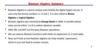
36. Problem
Minimize the following Boolean expression using Boolean identities
F(A,B,C)=AB+BC+BC+ABC
Given F(A,B,C)=AB+BC+BC+ABC
F(A,B,C)=AB+B(C+C)+ABC
F(A,B,C)=AB+B.1+ABC
= AB+B+ABC [B.1=B]
= B(A+1)+ABC [A+1=1]
= B+ABC [Apply distributive law A+BC=(A+B)(A+C)]
= (B+B)(B+AC) [B+B=1]
= B+AC
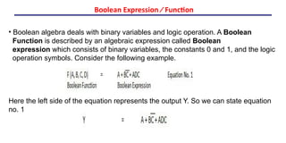
37. Problem
Minimize the following Boolean expression using Boolean identities
F(A,B,C)=(A+B)(A+C)
Given, F(A,B,C)=(A+B)(A+C)
F(A,B,C)=A.A+A.C+B.A+B.C
=A+AC+AB+BC [A.A=A]
= A(1+C+B)+BC [1+Anything=1]
= A+BC
39. Boolean algebra deals with binary variables and logic operation. A Boolean
Function is described by an algebraic expression called Boolean
expression which consists of binary variables, the constants 0 and 1, and the logic
operation symbols. Consider the following example.
Here the left side of the equation represents the output Y. So we can state equation
no. 1
Boolean Expression Function
40. A truth table represents a table having all combinations of inputs and their
corresponding result.
It is possible to convert the switching equation into a truth table. For example,
consider the following switching equation.
The output will be high (1) if A = 1 or BC = 1 or both are 1. The truth table for this
equation is shown by Table (a). The number of rows in the truth table is 2n
where
n is the number of input variables (n=3 for the given equation). Hence there are
23
= 8 possible input combination of inputs.
Truth Table Formation
42. It is in the form of sum of three terms AB, AC, BC with each individual term is a
product of two variables. Say A.B or A.C etc. Therefore such expressions are
known as expression in SOP form.
The sum and products in SOP form are not the actual additions or multiplications.
In fact they are the OR and AND functions.
In SOP form, 0 represents a bar and 1 represents an unbar. SOP form is
represented by Given below is an example of SOP.
Sum of Products (SOP) Form