CAD CAM Exercise CNC PROGRAMMING LATHE.pptx
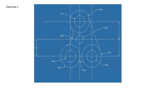
- 1. Exercise-1
- 2. Exercise-2
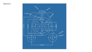
- 3. Exercise-3
- 4. Exercise-4
- 6. Introduction CNC ’ü▒ Form of programmable automation. ’ü▒ Mechanical actions of machine tool are controlled by program. ’ü▒ The program is in form of alphanumeric data. ’ü▒ After a job is finished the program of instructions can be changed to process a new job.
- 7. ŌĆó *The first NC machines were built in the 1940s and 1950s by Prof. John T Parson. ŌĆó *CNC machine came into existence after evolution of computer around 1980. ŌĆó *Modern CNC Machine are improving further as the technology is changing with a variety of functions according to applications. History of CNC
- 8. *A CNC machine consist of following 6 major elements: i. Input Device ii. Machine Control Unit iii. Machine Tool iv. Driving System v. Feedback Devices vi. Display Unit Elements of CNC machine
- 9. *The tool or material moves automatically. *Tools can operate in 1-5 axes. *Larger machines have a machine control unit (MCU) which manages operations. *Movement is controlled by motors (actuators). *Feedback is provided by sensors (transducers) *Tool magazines are used to change tools automatically. Features of CNC machine
- 11. Block Diagram CNC machine
- 12. ’üČThe part program is a sequence of instructions, which describe the work, which has to be done on a part, in the form required by a computer under the control of a numerical control computer program. It is the task of preparing a program sheet from a drawing sheet. All data is fed into the numerical control system using a standardized format. ’üČProgramming is where all the machining data are compiled and where the data are translated into a language which can be understood by the control system of the machine tool. The machining data is as follows: ’üČMachining sequence classification of process, tool start up point, cutting depth, tool path, etc. ’üČCutting conditions, spindle speed, feed rate, coolant, etc. ’üČSelection of cutting tools. Part programming of CNC machine
- 13. While preparing a part program, need to perform the following steps: ’üČDetermine the startup procedure, which includes the extraction of dimensional data from part drawings and data regarding surface quality requirements on the machined component. ’üČSelect the tool and determine the tool offset. ’üČSet up the zero position for the workpiece. ’üČSelect the speed and rotation of the spindle. ’üČSet up the tool motions according to the profile required. ’üČReturn the cutting tool to the reference point after completion of work. ’üČEnd the program by stopping the spindle and coolant. Part programming of CNC machine
- 14. ’üČ The part programming contains the list of coordinate values along the X, Y and Z directions of the entire tool path to finish the component. ’üČ The program should also contain information, such as feed and speed. Each of the necessary instructions for a particular operation given in the part program is known as an NC word. ’üČ A group of such NC words constitutes a complete NC instruction, known as block. ’üČ The most common codes used when programming NC machines tools are G-codes (preparatory functions), and M codes (miscellaneous functions). Other codes such as F, S, D, and T are used for machine functions such as feed, speed, cutter diameter offset, tool number, etc. Part programming of CNC machine
- 15. Part programming of CNC machine
- 16. *O - Program number (Used for program identification) *N - Sequence number (Used for line identification) *G - Preparatory function *X - X axis designation *Y - Y axis designation *Z - Z axis designation *R - Radius designation *F ŌĆō Feed rate designation *S - Spindle speed designation *H - Tool length offset designation *D - Tool radius offset designation *T - Tool Designation *M - Miscellaneous function Part programming Key latters
- 17. *Controlled by G and M codes. *These are number values and co-ordinates. *Each number or code is assigned to a particular operation. *Typed in manually to CAD by machine operators. *G & M codes are automatically generated by the computer software. How CNCworks
- 18. 1. Prepare the drawing of the job required as per the dimensions. 2. Write a part program for the job to be machined on the CNC turning machine. 3. Place the job in the chuck and set the tool according to the operation to be performed on the machine. 4. Close the door of the CNC machine after the placement of the workpiece. 5. Start the machine and run the program. 6. Remove the job after completion of the work. Procedure
- 19. G00 Rapid Transverse G01 Linear Interpolation G02 Circular Interpolation, CW G03 Circular Interpolation, CCW G17 XY Plane,G18 XZ Plane,G19 YZ Plane G20/G70 Inch units G21/G71 Metric Units G40 Cutter compensation cancel G41 Cutter compensation left G42 Cutter compensation right G43 Tool length compensation (plus) G43 Tool length compensation (plus) G44 Tool length compensation (minus) G49 Tool length compensation cancel G80 Cancel canned cycles G81 Drilling cycle G82 Counter boring cycle G83 Deep hole drilling cycle G90 Absolute positioning G91 Incremental positioning Important G codes
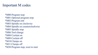
- 20. *M00 Program stop *M01 Optional program stop *M02 Program end *M03 Spindle on clockwise *M04 Spindle on counterclockwise *M05 Spindle stop *M06 Tool change *M08 Coolant on *M09 Coolant off *M10 Clamps on *M11 Clamps off *M30 Program stop, reset to start Important M codes


