Canal structures
- 1. Canal Structures Prof. Manjunath. B Assistant Professor Sanjivani College of Engineering Kopargaon
- 2. Contents ï Introduction ï Mechanism of Regulation Works ï Canal Falls ï Cross regulator ï Distributary Head Regulator ï Canal escapes ï Canal Outlets
- 3. Introduction ï The structure constructed on a canal to regulate the discharge, full supply level or velocity of flow are known as Canal Regulation Works. ï A canal obtains its share of water from the pool behind a barrage through a structure called the Canal Head Regulator. Through this is also a regulation structure for controlling the amount of water passing into the canal.
- 4. Advantages of Regulation Works I. Canal fall is used to reduce energy of water due to velocity of u/s water. II. Cross Regulator is use for maintain supply of water to off- taking channel during low discharge period. III. With combination of canal fall, it is possible to control water surface slope. IV. Distributary Head Regulator is use as a silt control device and prevents the deposition of silt in canal. V. Canal Escape enables to maintain proper head in canal during heavy rainfall period or low demand time. VI. Canal outlet act as water measuring device and it is helpful to make water charge bills according to field utilization.
- 5. Canal Falls A canal fall is an irrigation structure constructed across a canal to lower down its water level and destroy the surplus energy liberated from the falling water which my otherwise scour the bed and banks of canal. ïķNecessity of Canal Falls: The canal falls are required when the natural slope of the ground along the canal alignment is steeper than the bed slope of the canal. The canal bed slope my vary from 1 in 4000 for a discharge of bout 1.5 cumecs to about 1 in 8000 for a discharge of 3000 cumecs. The average ground slope is about 1 in 200 to 1 in 50. The difference in the slops is adjusted by providing vertical falls in the bed of the canal at suitable intervals.
- 6. Location of Canal Falls ï For the canal which does not irrigate the area directly, the falls should be located from the consideration of economy of earthwork. ï For the canal irrigating the area directly, a fall may be provided at a location where the F.S.L. of the canal outstrips the ground level but before the bed of the canal comes into filling. ï The location of a falls may also be decided from the consideration of the possibility of combining it with a cross regulator or a rod bridge to effect economy. ï A relative economy is achieved by providing either a large number of small falls or small number of large falls, whichever is less is worked out. ï Sometimes it is necessary to provide fewer falls of large drops to enable hydropower generation at these falls.
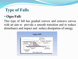
- 7. Type of Falls ï Ogee Fall: This type of fall has gradual convex and concave curves with an aim to provide a smooth transition and to reduce disturbance and impact and reduce dissipation of energy.
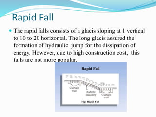
- 8. Rapid Fall ï The rapid falls consists of a glacis sloping at 1 vertical to 10 to 20 horizontal. The long glacis assured the formation of hydraulic jump for the dissipation of energy. However, due to high construction cost, this falls are not more popular.
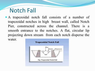
- 9. Notch Fall ï A trapezoidal notch fall consists of a number of trapezoidal notches in high breast wall, called Notch Pier, constructed across the channel. There is a smooth entrance to the notches. A flat, circular lip projecting down stream from each notch disperse the water.
- 10. Vertical Drop Fall ï In this, a crest wall is constructed to create a vertical drop. Cistern is provided to dissipate the surplus energy of water leaving crest. In cistern a grid of banks of timber placed a few centimeters apart to intercept the falling nappe. This fall is not become popular due to getting clogged with floating debris.
- 11. Glacis Fall The glacis fall utilizes hydraulic jump for the dissipation of energy. Following are the type of Glacis fall: Straight Glacis: In Punjab, the flumed fall with straight glacis was developed. There was some problem with some of these falls. Like one cause of trouble was that even after the formation of hydraulic jump, there was considerable amount of surplus energy in water.
- 12. ï Glacis Fall
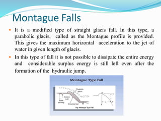
- 13. Montague Falls ï It is a modified type of straight glacis fall. In this type, a parabolic glacis, called as the Montague profile is provided. This gives the maximum horizontal acceleration to the jet of water in given length of glacis. ï In this type of fall it is not possible to dissipate the entire energy and considerable surplus energy is still left even after the formation of the hydraulic jump.
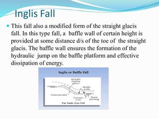
- 14. Inglis Fall ï This fall also a modified form of the straight glacis fall. In this type fall, a baffle wall of certain height is provided at some distance d/s of the toe of the straight glacis. The baffle wall ensures the formation of the hydraulic jump on the baffle platform and effective dissipation of energy.
- 15. Cross Regulators It is a structure constructed across a canal to regulate the water level in the canal upstream itself and the discharge passing downstream of it for one or more following purposes:- I. It enables effective regulation of the entire canal system. II. It helps in closing the supply to the d/s of the parent channel, for the purpose of repairs. III. There can be provided a bridge which can be means of communication. IV. It helps to absorb fluctuation in the various sections to the canal system, and thus prevents breaches in the tail reaches. V. It can be use to control the drawdown when the subsoil water level re high to ensure safety of canal lining. VI. In conjunction with escapes they help water to escape from the channels.
- 16. Distributary Head Regulator: A distributary head regulator is provided at the head of the off- taking canal to control the supplies entering the off-taking canal. The Distributary Head Regulator serves to:- I. Divert and regulate the supply into the distributary from the parent channel, II. Control the silt entering the distributary from the parent channel, III. Measure the discharge entering the distributary. IV. It help in shutting off the supplies when not needed in the off- taking channel or when off-taking channel is required to be closed for repairing works.
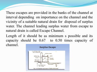
- 17. Canal Escape Canal escape is a structure to dispose of surplus or excess water from a canal. It is a sort of safety valve. It provides protection of the canal against possible damage due to excess supply which may be because of either mistake in releasing water or a heavy rainfall which cause decrease in demand of water for irrigation in the fields. The excess supply makes the canal banks vulnerable to breaches or dangerous leaks and hence, provision for disposing of excess supply in the form of canal escapes at suitable intervals along the canal. Types of Escapes: Based on the purpose: Surplus WaterEscape: It is a structure constructed on n irrigation channel to dispose of surplus ï water from the channel. It also known as Canal Surplus Escape.
- 18. These escapes are provided in the banks of the channel at interval depending on importance on the channel and the vicinity of a suitable natural drain for disposal of surplus water. The channel leading surplus water from escape to natural drain is called Escape Channel. Length of it should be as minimum s possible and its capacity should be 0.67 to 0.50 times capacity of channel.
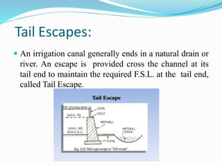
- 19. Tail Escapes: ï An irrigation canal generally ends in a natural drain or river. An escape is provided cross the channel at its tail end to maintain the required F.S.L. at the tail end, called Tail Escape.
- 20. Based on the Structural Design Rectangular Type or Sluice Type Escapes: It is also use s surplus escapes. These sluices can empty the canal for repair and maintenance and, is some cases, act as scouring sluice to facilitate removal of sediment. Location of escapes depends on the availability of suitable drains, depressions or river bed level. Weir Type Escape: These are flush or weir escapes constructed either in masonry or concrete with or without crest shutter which re capable of disposing of surplus water from the canal.
- 21. Canal Outlet When the canal water reached near the fields to be irrigated, it has to be transferred to the watercourse.at the junction of watercourse and distributary, an outlet is provided. It is a masonry structure through which water is admitted from the distributary into watercourse. It also act as water- measuring device. The discharge through an outlet is less than 0.085 cumecs. Thus, an outlet is like a head regulator for field channel. Requirements of a good Outlet: i. It should be simple in design with no moving parts, in construction and maintenance. ii. It should be strong and durable. iii. It should not be easily tampered with by the cultivators, but if tampered with it should be easily detected. iv. It should be worked efficiently with a small working head. v. For proper distribution of water the outlet should draw proportionately more or less discharge with the varying supply I the distributing channel.

