


Capstone Design Final Report
- 1. Design, Fabrication, and Integration of an Human-Powered Rover A Study of the Design and Manufacturing Processes for the 2019 NASA Human Exploration Rover Challenge Written by: Zachary Adams; Matthew Bartholomew; Jack Carstens; Parker Ensing; Daniel Epstein; Andrew Liquori; Grant MacNeil; Anatole Roper Dr. Ramana Pidaparti MCHE 4920 Spring 2019
- 2. Introduction As the United States revamps its space program, with plans to return to the moon and eventually send people to Mars, innovations in transportation technology will build the foundation for human exploration missions and scientific surveys. With this necessity in mind, NASA hosts the annual Human Exploration Rover Challenge (HERC), where university and high school students build human-powered vehicles to handle the simulated terrain of Mars. The goal of our team was to design and fabricate a variety of subsystems essential to the roverŌĆÖs performance. Over the course of the past year, we have developed the chassis, drivetrain, wheels, and steering for a rover which will enter in the 2020 competition. The design process began with constraints set by NASA. With those constraints in mind, we analyzed the previous UGA rover for ways to improve the design. Once design goals were set in place, each subsystem team created plans for fabrication. After final designs had been settled on, materials were purchased. The team then used the remainder of the project time to build and test the subsystems. With these critical systems completed, the 2020 UGA team will have an excellent starting point and a strong foundation for success at next yearŌĆÖs competition. Competition Objectives Our main objective was to design, machine, and fabricate a rover and compete in the NASA Human Exploration Rover Challenge. This process began with improving the previous rover design by making the chassis lighter, redesigning the wheels, drive train, steering, suspension, and brakes. Most of our constraints came from the Rover Challenge Guidelines, which was issued by NASA for the competition. The guidelines delineate all design constraints in detail. Some of the major constraints are that 2 people must fit on the rover, the rover needs be collapsable to fit in a 5ŌĆÖ x 5ŌĆÖ x 5ŌĆÖ box and it must have a 15ŌĆØ ground clearance. All design constraints and competition objectives are assigned point values, so the ultimate goal is to score as highly as possible in the competition. Introduction to Subsystems In order to design and fabricate an ergonomic, functional, and lightweight rover, our team divided the workload into smaller subsystems. As a team we established that the rover would consist of six primary systems; chassis, wheels, drivetrain, suspensions, brakes, and steering. The core of the rover and the most important subsystem is the chassis. This serves as the structural framework of the rover and must support the attachment and integration of the remaining systems. The wheels of the rover will be mounted to an axle below the rover chassis and enable the rover to navigate across the simulated Mars terrain. Drivetrain, suspension,
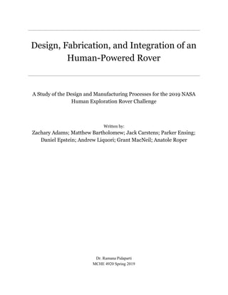
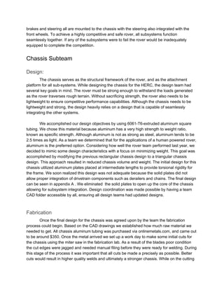
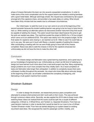
- 3. brakes and steering all are mounted to the chassis with the steering also integrated with the front wheels. To achieve a highly competitive and safe rover, all subsystems function seamlessly together. If any of the subsystems were to fail the rover would be inadequately equipped to complete the competition. Chassis Subteam Design: The chassis serves as the structural framework of the rover, and as the attachment platform for all sub-systems. While designing the chassis for the HERC, the design team had several key goals in mind. The rover must be strong enough to withstand the loads generated as the rover traverses rough terrain. Without sacrificing strength, the rover also needs to be lightweight to ensure competitive performance capabilities. Although the chassis needs to be lightweight and strong, the design heavily relies on a design that is capable of seamlessly integrating the other systems. We accomplished our design objectives by using 6061-T6-extruded aluminum square tubing. We chose this material because aluminum has a very high strength to weight ratio, known as specific strength. Although aluminum is not as strong as steel, aluminum tends to be 2.5 times as light. As a team we determined that for the applications of a human powered rover, aluminum is the preferred option. Considering how well the rover team performed last year, we decided to mimic some design characteristics with a focus on minimizing weight. This goal was accomplished by modifying the previous rectangular chassis design to a triangular chassis design. This approach resulted in reduced chassis volume and weight. The initial design for this chassis utilized aluminum plates placed at intermediate lengths to provide torsional rigidity for the frame. We soon realized this design was not adequate because the solid plates did not allow proper integration of drivetrain components such as derailers and chains. The final design can be seen in appendix A . We eliminated the solid plates to open up the core of the chassis allowing for subsystem integration. Design coordination was made possible by having a team CAD folder accessible by all, ensuring all design teams had updated designs. Fabrication Once the final design for the chassis was agreed upon by the team the fabrication process could begin. Based on the CAD drawings we established how much raw material we needed to get. All chassis aluminum tubing was purchased via onlinemetals.com, and came out to be around $350. Once the metal arrived we set up a work day to make some initial cuts for the chassis using the miter saw in the fabrication lab. As a result of the blades poor condition the cut edges were jagged and needed manual filing before they were ready for welding. During this stage of the process it was important that all cuts be made a precisely as possible. Better cuts would result in higher quality welds and ultimately a stronger chassis. While on the cutting
- 4. phase of chassis fabrication the team ran into several unexpected complications. In order to make some of the more complicated cuts for the support beams we needed a working bandsaw with a good metal blade. Although seemingly simple, this request was overlooked by lab support amongst all of the capstone chaos, and provided a two week delay on cutting. What should have taken thirty minutes took two weeks due to unforeseen circumstances. Our initial hopes to weld the rover on our own came to an end at the beginning of the second semester because the student welding teacher was going to be too busy to have time to train us. While seeking out alternate options we discovered another instrument shop that would be capable of welding the chassis. This option would have been ideal however the price to get the work we needed was steep. The machinist quoted the project at $45/hr for a 16 hour project which came out to an additional $720. This option was clearly not in the projects budget. As the final weeks for capstone were closing in, we reached out to Dr. Hilten to see if he could help us out in any way. We were put in touch with Reece, a student capable of welding the chassis. After coordinating a meeting with him we were finally going to have half of the chassis completed. Reece was able to weld the chassis in time for the capstone showcase but unfortunately we did not have the time to make the other half. Conclusion The chassis design and fabrication was a great learning experience, and a great way to put our knowledge of engineering to use. Unfortunately as a team we fell short of realizing our design but have learned much more about how a real world project may flow. Many engineering design problems are much more complex than they initially seem. As a result completion of tasks and fabrication take longer than anticipated. In addition to complexity issues there were unforeseen hurdles throughout the semester. As a team who knew little about vehicular design at the beginning of the year, we all better understand the complexity of designing, and fabricating a multi system machine from scratch. Drivetrain Subteam Design In order to design the drivetrain, we researched previous years competitors and attempted to analyze what worked and didnŌĆÖt work well on their rovers. This was achieved through numerous videos online. Secondly, we also applied the 2019 rules to these rovers. After watching these videos we realized that the rovers could be split into a couple of different categories: 2-Wheel vs. 4-Wheel Drive, and Tandem vs. Separate Drivetrains. From here we used decision matrices in order to decide that it would be best for our rover to be a 2-Wheel Tandem Drivetrain model. From here we started designing our system based on existing recumbent style bikes. We recognized the need for passenger comfort, mobility, and
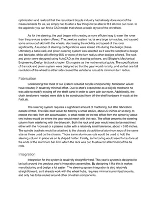
- 5. optimization and realized that the recumbent bicycle industry had already done most of the measurements for us, we simply had to alter a few things to be able to fit it all onto our rover. In the appendix you can find a CAD model that shows a basic layout of the drivetrain. As for the steering, the goal began with creating a more efficient way to steer the rover than the previous system offered. The previous system had a very large turn radius, and caused some amount of skid with the wheels, decreasing the mobility and speed of the rover significantly. A number of steering configurations were looked into during the design phase. Ultimately a basic rack and pinion steering system was selected as it was the simplest to design and fabricate, while still offering 95% or more of the turn radius other designs offered. The rack and pinion were designed using AutoCAD as the drawing software, and ShigleyŌĆÖs Mechanical Engineering Design textbook chapter 13 on gears as the mathematical guide. The specifications of the rack and pinion system were designed so that the gear would not slip, and so that one full revolution of the wheel to either side caused the vehicle to turn at its minimum turn radius. Fabrication Considering that most of our system included bicycle componentry, fabrication would have resulted in relatively minimal effort. Due to MattŌĆÖs experience as a bicycle mechanic he was able to modify existing off-the-shelf parts in order to work with our rover. Additionally, the chain tensioners needed were able to be constructed from off-the-shelf hardware in-stock at the FabLab. The steering system requires a significant amount of machining, but little fabrication outside of that. The rack itself would be held by a small sleeve, about 20 inches or so long, to protect the rack from dirt accumulation. A small notch on the top offset from the center by about two inches would be where the gear would mesh with the rack. The offset prevents the steering column from interfering with the drivetrain. Both the rack and gear would need to be machined either with the hydro-jet or a plasma cutter with a relatively small tolerance, about 0.05 inches.┬▒ The spindle brackets would be attached to the chassis via additional aluminum rods of the same size as those used on the chassis. Those same aluminum rods would be used to hold the steering column in place via an A shaped holder. Finally, some boring would need to be done at the ends of the aluminum bar from which the rack was cut, to allow for attachment of the tie rods. Integration Integration for the system is relatively straightforward. This yearŌĆÖs system is designed to be built around the previous yearŌĆÖs integration assemblies. By designing it like this is makes manufacturing and design a lot easier. The steering system integration is also relatively straightforward, as it already work with the wheel hubs, requires minimal customized mounts, and only has to be routed around other drivetrain components.
- 6. As for the steering system, the supports for the spindle brackets and steering column, along with the sleeve for the rack, are used to hold the steering in place and integrate it with the rest of the rover. The spindle bracket hold spindles that would connect the tie rods on the rack to the spindles, which rotate about a steel bolt. The spindles are connected to the wheel hub, and rotation of the spindles rotates the wheel itself. Conclusion As a whole, we had an excellent learning opportunity designing and planning our drivetrain subsystem. Deciding our seating arrangements, 2 vs 4-Wheel Drive, and steering allowed us to apply engineering knowledge we have acquired throughout our college careers. Focusing on efficiency, speed, and simplicity, we were able to come to a final design using a 2-Wheel Tandem Drivetrain with rack and pinion steering. Using prior experience with fabrication and biking, our team was able to formulate a process for manufacturing. The fabrication lab at UGA helped our process for fabrication and integration of drivetrain, wheels, and steering. Wheel Subteam Design Initial design brainstorming led to a wide variety of wheel options, ranging from spoke wheels to tank treads to a Strandbeest-style creation. All of these designs went into design decision matrices where they were compared and scored based on weighted categories. The designs that survived the matrices were then compared to one another until a design had been selected. The weighted categories emphasized designs which met competition criteria and were straightforward to fabricate. These categories, listed in order of importance, were: weight, price, ease of fabrication, traction, durability, versatility, size, ease of integration, comfort, originality, and complexity. The chosen design scored highest in the price and durability categories while scoring high points generally in all categories. Known as the ŌĆ£loop-spokeŌĆØ design, the chosen design featured asymmetrical ellipses which connected the wheel hub to the rim. Curved spokes would, in theory, provide a degree of shock absorption by allowing the metal to flex during periods of rough terrain or increased vibrations in the rover. Although this theory remains untested, our team wished to pursue the concept to better understand how the curved spokes would mitigate vibration and discomfort in the rover and for the novelty of the design. Fabrication Although prototypes of the wheels were never completed, a variety of materials were ordered and can be passed on to the subsequent team. In total, several feet of aluminum bar stock (Ōģ£ŌĆØ x 3ŌĆØ) and two rubber floor mats were purchased. The bar stock would have been used to fabricate the rims of each wheel. The intent was to use the heavy rollers in the fabrication shop to circularize the bar stock. By the time the aluminum arrived, the team lacked the time left
- 7. to reserve the rollers for use. The standing recommendation for the next team is to use this aluminum and the rollers. Enough material was ordered for 40ŌĆØ diameter rims on each wheel, with some leftover to be used on other parts of the rover. If the next team maintains this design constraint, they should be able to fabricate the wheel rims early into the projectŌĆÖs timeline. Additionally, some of this leftover aluminum could be used to fabricate attachment points for the curved spokes. By salvaging the wheel hubs off of the old rover, we intended to weld attachment points between the scrap aluminum and the hubs to form slots where the loops would slide into and get bolted down. The precise design for these attachment points was never officially completed or agreed upon, so the next team has design flexibility here. Regardless of their solution to mounting the spokes, our team recommends continuing to use the old hubs. They are well machined, and recycling these parts will save development time and costs. Tread requirements primarily involved being able to handle various obstacles, such as deep sand and boulders. To accommodate these challenges, rubber tires would be ideal due to their flexibility and durability. Despite this, premade rubber tires or tire components were not acceptable according to the 2019 HERC guidelines. Instead of using premade tires, the team chose to cut rubber bar mats into strips that matched the wheelsŌĆÖ circumference and width. The large indentations in the rubber mats made for excellent treads, since small bits of debris would not stick into the rubber or collect in any small grooves. Aside from the form factor, the rubber mats were sturdy and seemed like a durable choice. Once the mats arrived, our team sliced them into appropriately-sized strips. At the time of writing, these strips are ready to be use, so they should be acceptable for the next teamŌĆÖs rover. Integration Integration between the wheels and the drivetrain would rely on the axles from the old rover since they already matched with the hubs that would be reused. This axle system provided the means for the wheels to receive power from the drivetrain components via mechanical fasteners attached radially around the axles.Similarly, this fastener system would be used to mount the wheels to the steering assembly. Outside of these details, however, no designs were completed regarding the specific hardpoints required to support the wheel structurally. Again, the intent was to repurpose old rover hardware to meet these needs, although techniques were not decided upon in an official manner. Conclusion As things stand presently, enough materials and design ideas exist for the next team to immediately begin work on completing the wheel fabrication. Although there is interest among our team members in having the loop spoke design be fabricated by the next team, there are no explicit reasons that the following team needs to do so. The rim material could be used to accommodate practically any new wheel design if need be. Similarly, the hubs could still be reused to support future designs.
- 8. Conclusion During the course of the 2018-2019 academic year, our group completed the task of designing the critical subsystems of a human-powered Mars rover as well as the initial phases of fabrication. We achieved this by dividing our team into subteams and tackling the design and manufacturing process as smaller, more focused groups. Integration of the parts was a team effort as there are many intricacies. This came into play most frequently during fabrication, as individuals across the various subteams would regroup to make meaningful progress. We learned throughout this process to better budget our time, especially since obstacles will always appear in a project as large as this one. With the time, infrastructure, and help given to us we completed as much as possible and have set up next yearŌĆÖs team to be a competitor in the 2020 Human Exploration Rover Challenge. Appendix Appendix A: Figures Figure 1.ŌĆŗ Chassis Final Rendering
- 9. Figure 2.ŌĆŗ Front View of Chassis Figure 3.ŌĆŗ Chassis with Drivetrain Integration
- 10. Figure 4. ŌĆŗRack and Pinion Steering Rendering
- 11. Figure 5. ŌĆŗFinal Chassis with Welded Construction