Ch06a
- 1. CHAPTER6 Cam Design THEORY OF MACHINES AND MECHANISMS John J. Uicker, Jr. / Gordon R. Pennock Joseph E. Shigley Copyright ┬® 2011 by Oxford University Press, Inc.
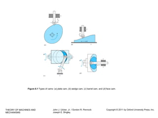
- 2. Figure 6.1 Types of cams: (a) plate cam, (b) wedge cam, (c) barrel cam, and (d) face cam. THEORY OF MACHINES AND MECHANISMS John J. Uicker, Jr. / Gordon R. Pennock Joseph E. Shigley Copyright ┬® 2011 by Oxford University Press, Inc.
- 3. Figure 6.2 Plate cams with (a) an offset reciprocating knife-edge follower, (b) a reciprocating flatface follower, (c) an oscillating roller follower, and (d) an oscillating curved-shoe follower. THEORY OF MACHINES AND MECHANISMS John J. Uicker, Jr. / Gordon R. Pennock Joseph E. Shigley Copyright ┬® 2011 by Oxford University Press, Inc.
- 4. Figure 6.3 (a) Constant-breadth cam with a reciprocating flat-face follower. (b) Conjugate cams with an oscillating roller follower. THEORY OF MACHINES AND MECHANISMS John J. Uicker, Jr. / Gordon R. Pennock Joseph E. Shigley Copyright ┬® 2011 by Oxford University Press, Inc.
- 5. Figure 6.4 Displacement diagram for a cam. THEORY OF MACHINES AND MECHANISMS John J. Uicker, Jr. / Gordon R. Pennock Joseph E. Shigley Copyright ┬® 2011 by Oxford University Press, Inc.
- 6. Figure 6.5 Parabolic motion displacement diagram: (a) interfaces with uniform motion and (b) graphical construction. THEORY OF MACHINES AND MECHANISMS John J. Uicker, Jr. / Gordon R. Pennock Joseph E. Shigley Copyright ┬® 2011 by Oxford University Press, Inc.
- 7. Figure 6.6 Simple harmonic motion displacement diagram; graphical construction. THEORY OF MACHINES AND MECHANISMS John J. Uicker, Jr. / Gordon R. Pennock Joseph E. Shigley Copyright ┬® 2011 by Oxford University Press, Inc.
- 8. Figure 6.7 Cycloidal motion displacement diagram; graphical construction. THEORY OF MACHINES AND MECHANISMS John J. Uicker, Jr. / Gordon R. Pennock Joseph E. Shigley Copyright ┬® 2011 by Oxford University Press, Inc.
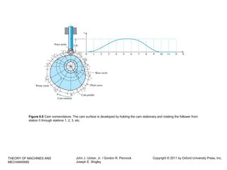
- 9. Figure 6.8 Cam nomenclature. The cam surface is developed by holding the cam stationary and rotating the follower from station 0 through stations 1, 2, 3, etc. THEORY OF MACHINES AND MECHANISMS John J. Uicker, Jr. / Gordon R. Pennock Joseph E. Shigley Copyright ┬® 2011 by Oxford University Press, Inc.
- 10. Figure 6.9 Graphical layout of a plate cam profile with an offset reciprocating roller follower. THEORY OF MACHINES AND MECHANISMS John J. Uicker, Jr. / Gordon R. Pennock Joseph E. Shigley Copyright ┬® 2011 by Oxford University Press, Inc.
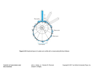
- 11. Figure 6.10 Graphical layout of a plate cam profile with a reciprocating flat-face follower. THEORY OF MACHINES AND MECHANISMS John J. Uicker, Jr. / Gordon R. Pennock Joseph E. Shigley Copyright ┬® 2011 by Oxford University Press, Inc.


