
Chapter 2 strength of materials II .pptx
- 1. ADAMA SCIENCE AND TECHNOLOGY UNIVERSITY SCHOOL OF MECHANICAL, CHEMICALAND MATERIAL ENGINEERING DEPARTMENT OF MECHANICAL ENGINEERING STRENGTH OF MATERIALS II; MEng3207 CHAPTER- 2 Transformations of Stress and Strain Prepared by: Mr. Kemal Temam (MSc) 22/05/2024 November, 2023
- 2. Contents ?Introduction ?Transformation of plane stress ?MohrĪ»s circle for plane stress ?General state of stress and three-dimensional analysis of stress ?Theories of failure ?Stresses in thin walled pressure vessels ?Transformation of plane strain ?Measurements of strain; strain rosette
- 3. Objectives ? Apply stress transformation equations to plane stress situations to determine any stress component at a point. ? Apply the alternative Mohr's circle approach to perform plane stress transformations. ?Use transformation techniques to identify key components of stress, such as principal stresses. ?Extend Mohr's circle analysis to examine three-dimensional states of stress. ?Examine theories of failure for ductile and brittle materials. ?Analyze plane stress states in thin-walled pressure vessels. ? Extend Mohr's circle analysis to examine the transformation of strain.
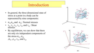
- 4. Introduction ? In general, the three dimensional state of stress at a point in a body can be represented by nine components: ? ?xx?yy and ?zz: Normal stresses ? ?xy ?yx ?xz ?zx ?yz and ?zy : Shear stresses ? By equilibrium, we can show that there are only six independent components of the stress ?xx ,?yy ,?zz ,?xy, ?xz, and ?yz
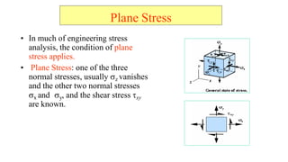
- 5. Plane Stress ? In much of engineering stress analysis, the condition of plane stress applies. ? Plane Stress: one of the three normal stresses, usually ?z vanishes and the other two normal stresses ?x and ?y, and the shear stress ?xy are known.
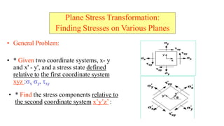
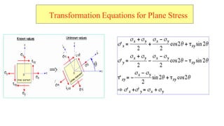
- 6. Plane Stress Transformation: Finding Stresses on Various Planes ? General Problem: ? * Given two coordinate systems, x- y and x' - y', and a stress state defined relative to the first coordinate system xyz :?x ?y, ?xy ? * Find the stress components relative to the second coordinate system xĪ»yĪ»zĪ» :
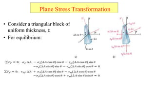
- 7. ? Consider a triangular block of uniform thickness, t: ? For equilibrium: Plane Stress Transformation
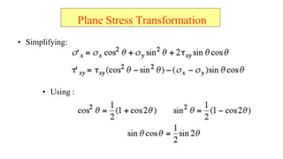
- 8. ? Simplifying: ? Using : Plane Stress Transformation
- 9. Transformation Equations for Plane Stress
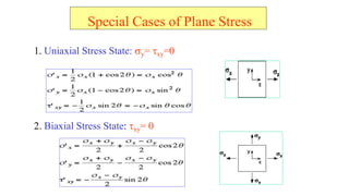
- 10. Special Cases of Plane Stress 1. Uniaxial Stress State: ?y= ?xy=0 2. Biaxial Stress State: ?xy= 0
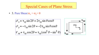
- 11. ? 3. Pure Shear:?x = ?y= 0 Special Cases of Plane Stress
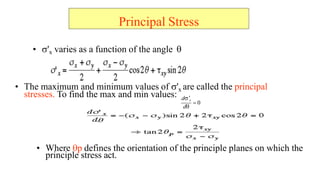
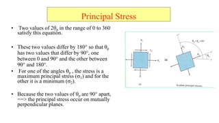
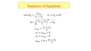
- 12. Principal Stress ? ?'x varies as a function of the angle ? ? The maximum and minimum values of ?'x are called the principal stresses. To find the max and min values: ? Where ?p defines the orientation of the principle planes on which the principle stress act. ? 0 d??x d?
- 13. ? Two values of 2?p in the range of 0 to 360 satisfy this equation. ? These two values differ by 180ĪŃ so that ?p has two values that differ by 90ĪŃ, one between 0 and 90ĪŃ and the other between 90ĪŃ and 180ĪŃ. ? For one of the angles ?p , the stress is a maximum principal stress (?1) and for the other it is a minimum (?2). ? Because the two values of ?p are 90ĪŃ apart, ==> the principal stress occur on mutually perpendicular planes. Principal Stress
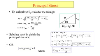
- 14. ? To calculate ?p consider the triangle Principal Stress ? Subbing back in yields the principal stresses: ? OR where
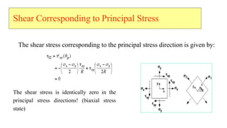
- 15. The shear stress corresponding to the principal stress direction is given by: The shear stress is identically zero in the principal stress directions! (biaxial stress state) Shear Corresponding to Principal Stress
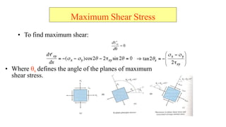
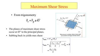
- 16. Maximum Shear Stress ? To find maximum shear: ? Where ?s defines the angle of the planes of maximum shear stress. ? 0 d?? d? xy
- 17. ? From trigonometry ? The planes of maximum shear stress occur at 45ĪŃ to the principal planes. ? Subbing back in yields max shear: Maximum Shear Stress
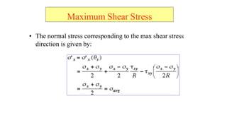
- 18. ? The normal stress corresponding to the max shear stress direction is given by: Maximum Shear Stress
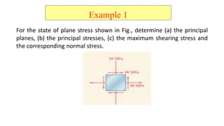
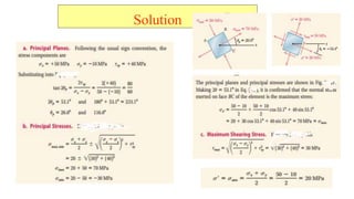
- 20. Example 1 For the state of plane stress shown in Fig., determine (a) the principal planes, (b) the principal stresses, (c) the maximum shearing stress and the corresponding normal stress.
- 21. Solution
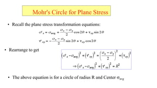
- 22. Mohr's Circle for Plane Stress ? Recall the plane stress transformation equations: ? Rearrange to get ? The above equation is for a circle of radius R and Center ?avg
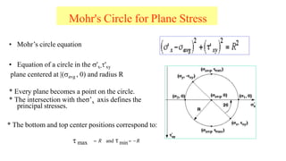
- 23. Mohr's Circle for Plane Stress ? MohrĪ»s circle equation ? Equation of a circle in the ?'x-?'xy plane centered at |(?avg , 0) and radius R * Every plane becomes a point on the circle. * The intersection with the?Ī»x axis defines the principal stresses. * The bottom and top center positions correspond to: ? R and ?min? ?R ? max
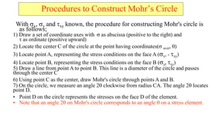
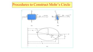
- 24. Procedures to Construct MohrĪ»s Circle With ?x, ?y and ?xy known, the procedure for constructing Mohr's circle is as follows; 1) Draw a set of coordinate axes with ? as abscissa (positive to the right) and ? as ordinate (positive upward) 2) Locate the center C of the circle at the point having coordinates(? aver, 0) 3) Locate point A, representing the stress conditions on the face A (?x, - ?xy) 4) Locate point B, representing the stress conditions on the face B (?y, ?xy) 5) Draw a line from point A to point B. This line is a diameter of the circle and passes through the center C 6) Using point C as the center, draw Mohr's circle through points A and B. 7) On the circle, we measure an angle 2? clockwise from radius CA. The angle 2? locates point D. ? Point D on the circle represents the stresses on the face D of the element. ? Note that an angle 2? on Mohr's circle corresponds to an angle ? on a stress element.
- 25. Procedures to Construct MohrĪ»s Circle
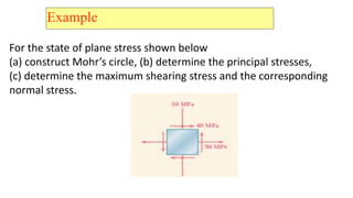
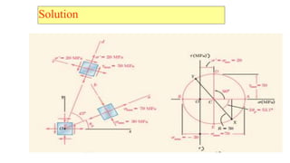
- 26. Example For the state of plane stress shown below (a) construct MohrĪ»s circle, (b) determine the principal stresses, (c) determine the maximum shearing stress and the corresponding normal stress.
- 27. Solution
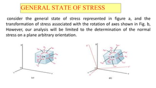
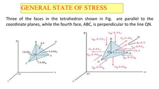
- 28. GENERAL STATE OF STRESS consider the general state of stress represented in figure a, and the transformation of stress associated with the rotation of axes shown in Fig. b, However, our analysis will be limited to the determination of the normal stress on a plane arbitrary orientation.
- 29. GENERAL STATE OF STRESS Three of the faces in the tetrahedron shown in Fig. are parallel to the coordinate planes, while the fourth face, ABC, is perpendicular to the line QN.
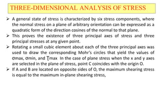
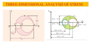
- 30. THREE-DIMENSIONAL ANALYSIS OF STRESS ? A general state of stress is characterized by six stress components, where the normal stress on a plane of arbitrary orientation can be expressed as a quadratic form of the direction cosines of the normal to that plane. ? This proves the existence of three principal axes of stress and three principal stresses at any given point. ? Rotating a small cubic element about each of the three principal axes was used to draw the corresponding MohrĪ»s circles that yield the values of ”ęmax, ”ęmin, and ?max In the case of plane stress when the x and y axes are selected in the plane of stress, point C coincides with the origin O. ? If A and B are located on opposite sides of O, the maximum shearing stress is equal to the maximum in-plane shearing stress,
- 31. THREE-DIMENSIONAL ANALYSIS OF STRESS
- 32. THEORIES OF FAILURE Failure of a member is defined as one of two conditions. 1.Fracture of the material of which the member is made. This type of failure is the characteristic of brittle materials. 2.Initiation of inelastic (Plastic) behavior in the material. This type of failure is the one generally exhibited by ductile materials. When an engineer is faced with the problem of design using a specific material, it becomes important to place an upper limit on the state of stress that defines the material's failure. If the material is ductile, failure is usually specified by the initiation of yielding, whereas if the material is brittle it is specified by fracture.
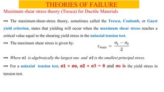
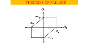
- 33. THEORIES OF FAILURE Maximum shear stress theory (Tresca) for Ductile Materials The maximum-shear-stress theory, sometimes called the Tresca, Coulomb, or Guest yield criterion, states that yielding will occur when the maximum shear stress reaches a critical value equal to the shearing yield stress in the uniaxial tension test. The maximum shear stress is given by: Where ”ę1 is algebraically the largest one and ”ę3 is the smallest principal stress. For a uniaxial tension test, ”ę1 = ”ęo, ”ę2 = ”ę3 = 0 and ”ęo is the yield stress in tension test.
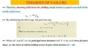
- 34. THEORIES OF FAILURE Therefore, shearing yield stress for yielding simple tension is equal to one-half of the tensile yield stress. By substituting the above eqn. into previous eqn. Where ”ę1Ī» and ”ę2Ī» are the principal stress deviators and Ī«kĪ» is the yield stress for pure shear i.e. the stress at which yielding occurs in pure shear torsion ”ę1 = - ”ę3.
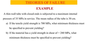
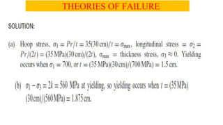
- 36. THEORIES OF FAILURE EXAMPLE A thin-wall tube with closed ends is subjected to a maximum internal pressure of 35 MPa in service. The mean radius of the tube is 30 cm. a) If the tensile yield strength is 700 MPa, what minimum thickness must be specified to prevent yielding? b) If the material has a yield strength in shear of = 280 MPa, what minimum thickness must be specified to prevent yielding?
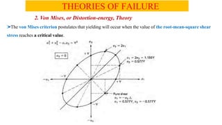
- 38. THEORIES OF FAILURE 2. Von Mises, or Distortion-energy, Theory The von Mises criterion postulates that yielding will occur when the value of the root-mean-square shear stress reaches a critical value.
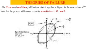
- 39. THEORIES OF FAILURE ? The Tresca and von Mises yield loci are plotted together in Figure for the same values of Y. Note that the greatest differences occur for ”┴ = ”ę3/”ę1 = ?1, 12 , and 2.
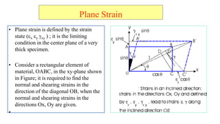
- 40. Plane Strain ? Plane strain is defined by the strain state (?x ?y ?xy ) ; it is the limiting condition in the center plane of a very thick specimen. ? Consider a rectangular element of material, OABC, in the xy-plane shown in Figure; it is required to find the normal and shearing strains in the direction of the diagonal OB, when the normal and shearing strains in the directions Ox, Oy are given. ?
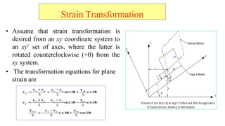
- 41. Strain Transformation ? Assume that strain transformation is desired from an xy coordinate system to an xy? set of axes, where the latter is rotated counterclockwise (+?) from the xy system. ? The transformation equations for plane strain are
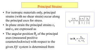
- 42. Principal Strains ? For isotropic materials only, principal strains (with no shear strain) occur along the principal axes for stress. ? In plane strain the principal strains ?1 and ?2 are expressed as ? The angular position ?p of the principal axes (measured positive counterclockwise) with respect to the given xy system is determined from
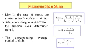
- 43. Maximum Shear Strain ? Like in the case of stress, the maximum in-plane shear strain is: which occurs along axes at 4?? from the principal axes, determined from ?s ? The corresponding average normal strain is
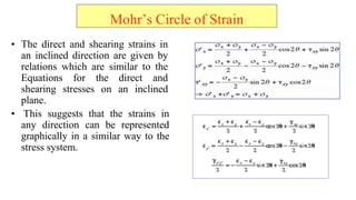
- 44. MohrĪ»s Circle of Strain ? The direct and shearing strains in an inclined direction are given by relations which are similar to the Equations for the direct and shearing stresses on an inclined plane. ? This suggests that the strains in any direction can be represented graphically in a similar way to the stress system.
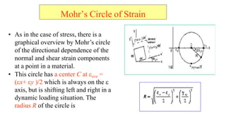
- 45. ? As in the case of stress, there is a graphical overview by MohrĪ»s circle of the directional dependence of the normal and shear strain components at a point in a material. ? This circle has a center C at ?ave = ??x+ ?y )/2 which is always on the ? axis, but is shifting left and right in a dynamic loading situation. The radius R of the circle is MohrĪ»s Circle of Strain
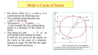
- 46. ? For given values of ?x, ?y and ?xy it is constructed in the following way: ? Two mutually perpendicular axes, ? and ?/2, are set up ? The points (?x, ?xy/2) and (?y, - ?xy /2) are located; the line joining these points is a diameter of the circle of strain. ? The values of ? and ? /2 in an inclined direction making an angle ? with Ox are given by the points on the circle at the ends of a diameter making an angle 2? with PQ; the angle 2? is measured clockwise. MohrĪ»s Circle of Strain
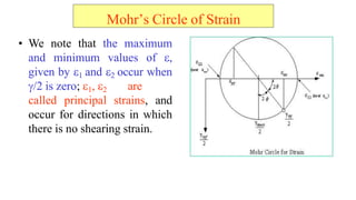
- 47. ? We note that the maximum and minimum values of ?, given by ?1 and ?2 occur when ?/2 is zero; ?1, ?2 are called principal strains, and occur for directions in which there is no shearing strain. MohrĪ»s Circle of Strain
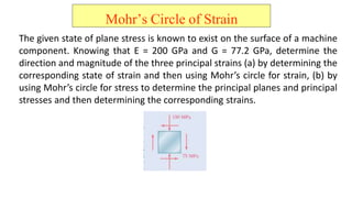
- 48. MohrĪ»s Circle of Strain The given state of plane stress is known to exist on the surface of a machine component. Knowing that E = 200 GPa and G = 77.2 GPa, determine the direction and magnitude of the three principal strains (a) by determining the corresponding state of strain and then using MohrĪ»s circle for strain, (b) by using MohrĪ»s circle for stress to determine the principal planes and principal stresses and then determining the corresponding strains.
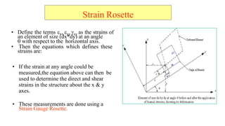
- 49. Strain Rosette ? Define the terms ?xx ?yy ?xy as the strains of an element of size (dx*dy) at an angle ? with respect to the horizontal axis. ? Then the equations which defines these strains are: ? If the strain at any angle could be measured,the equation above can then be used to determine the direct and shear strains in the structure about the x & y axes. ? These measurements are done using a Strain Gauge Rosette.
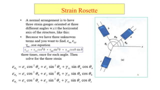
- 50. Strain Rosette
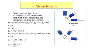
- 51. Strain Rosette
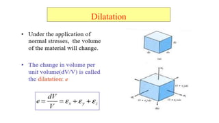
- 53. Dilatation
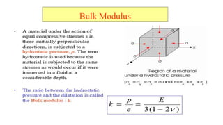
- 54. Bulk Modulus
- 55. THE END!