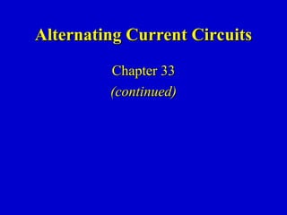
2. Phasor Diagrams
Vp
Ip
??t
Vp
Ip
??t
Vp Ip
??t
Resistor Capacitor Inductor
A phasor is an arrow whose length represents the amplitude of
an AC voltage or current.
The phasor rotates counterclockwise about the origin with the
angular frequency of the AC quantity.
Phasor diagrams are useful in solving complex AC circuits.
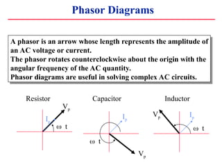
3. Reactance - Phasor Diagrams
Vp
Ip
??t
Vp
Ip
??t
Vp Ip
??t
Resistor Capacitor Inductor
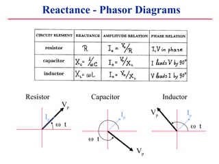
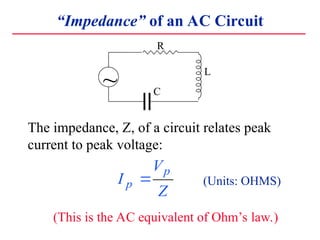
4. ˇ°Impedanceˇ± of an AC Circuit
R
L
C
~
The impedance, Z, of a circuit relates peak
current to peak voltage:
I
V
Z
p
p
? (Units: OHMS)
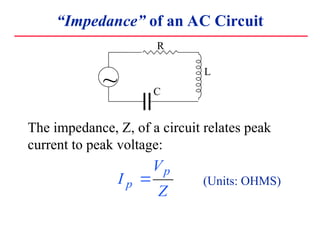
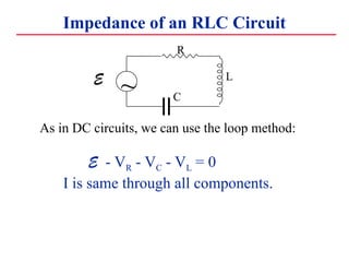
5. ˇ°Impedanceˇ± of an AC Circuit
R
L
C
~
The impedance, Z, of a circuit relates peak
current to peak voltage:
I
V
Z
p
p
? (Units: OHMS)
(This is the AC equivalent of OhmˇŻs law.)
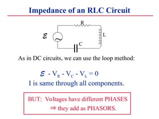
6. Impedance of an RLC Circuit
R
L
C
~
E
As in DC circuits, we can use the loop method:
E - VR - VC - VL = 0
I is same through all components.
7. Impedance of an RLC Circuit
R
L
C
~
E
As in DC circuits, we can use the loop method:
E - VR - VC - VL = 0
I is same through all components.
BUT: Voltages have different PHASES
? they add as PHASORS.
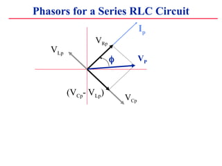
8. Phasors for a Series RLC Circuit
Ip
VRp
(VCp- VLp)
VP
?
VCp
VLp
9. Phasors for a Series RLC Circuit
By PythagorasˇŻ theorem:
(VP )2
= [ (VRp )2
+ (VCp - VLp)2
]
Ip
VRp
(VCp- VLp)
VP
?
VCp
VLp
10. Phasors for a Series RLC Circuit
By PythagorasˇŻ theorem:
(VP )2
= [ (VRp )2
+ (VCp - VLp)2
]
= Ip
2
R2
+ (Ip XC - Ip XL)2
Ip
VRp
(VCp- VLp)
VP
?
VCp
VLp
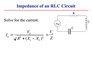
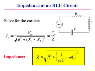
11. Impedance of an RLC Circuit
Solve for the current:
Ip ?
Vp
R2
? (Xc ? XL )2
?
Vp
Z
R
L
C
~
12. Impedance of an RLC Circuit
Solve for the current:
Impedance:
Ip ?
Vp
R2
? (Xc ? XL )2
?
Vp
Z
Z ? R2
?
1
?C
? ?L
??
??
??
??
2
R
L
C
~
13. The circuit hits resonance when 1/?C-?L=0: ??r=1/
When this happens the capacitor and inductor cancel each other
and the circuit behaves purely resistively: IP=VP/R.
Impedance of an RLC Circuit
Ip ?
Vp
Z
Z ? R
2
?
1
?C
? ?L
??
??
??
??
2
The currentˇŻs magnitude depends on
the driving frequency. When Z is a
minimum, the current is a maximum.
This happens at a resonance frequency:
LC
?
The current dies away
at both low and high
frequencies.
IP
0
1 0
2
1 0
3
1 0
4
1 0
5
R = 1 0 0 ?
R = 1 0 ?
?r
L=1mH
C=10?F
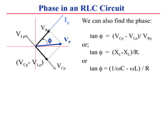
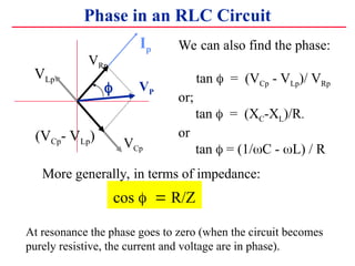
14. Phase in an RLC Circuit
Ip
VRp
(VCp- VLp)
VP
?
VCp
VLp
We can also find the phase:
tan ? = (VCp - VLp)/ VRp
or;
tan ? = (XC-XL)/R.
or
tan ? = (1/?C - ?L) / R
15. Phase in an RLC Circuit
At resonance the phase goes to zero (when the circuit becomes
purely resistive, the current and voltage are in phase).
Ip
VRp
(VCp- VLp)
VP
?
VCp
VLp
We can also find the phase:
tan ? = (VCp - VLp)/ VRp
or;
tan ? = (XC-XL)/R.
or
tan ? = (1/?C - ?L) / R
More generally, in terms of impedance:
cos ??? R/Z
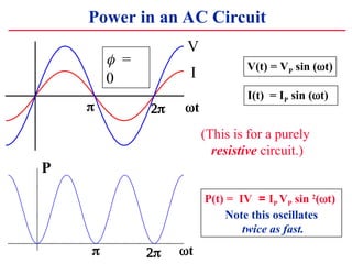
16. Power in an AC Circuit
V(t) = VP sin (?t)
I(t) = IP sin (?t)
P(t) = IV = IP VP sin 2
(?t)
Note this oscillates
twice as fast.
V
?t
? ??
I
?t
? ??
P
??=
0
(This is for a purely
resistive circuit.)
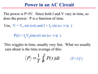
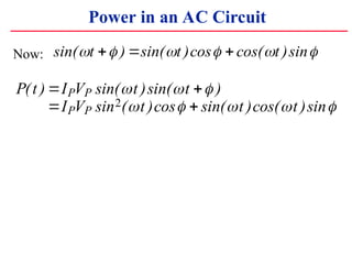
17. The power is P=IV. Since both I and V vary in time, so
does the power: P is a function of time.
Power in an AC Circuit
Use, V = VP sin (?t) and I = IP sin (??t+??) :
P(t) = IpVpsin(?t) sin (??t+??)
This wiggles in time, usually very fast. What we usually
care about is the time average of this:
P
T
P t dt
T
? ?
1
0
( ) (T=1/f )
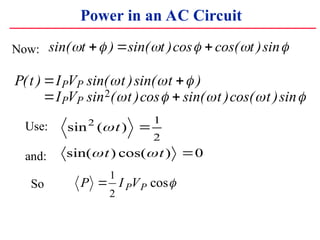
18. Power in an AC Circuit
Now: sin( ) sin( )cos cos( )sin
? ? ? ? ? ?
t t t
? ? ?
19. Power in an AC Circuit
P t I V t t
I V t t t
P P
P P
( ) sin( )sin( )
sin ( )cos sin( )cos( )sin
? ?
? ?
? ? ?
? ? ? ? ?
2
Now: sin( ) sin( )cos cos( )sin
? ? ? ? ? ?
t t t
? ? ?
20. Power in an AC Circuit
P t I V t t
I V t t t
P P
P P
( ) sin( )sin( )
sin ( )cos sin( )cos( )sin
? ?
? ?
? ? ?
? ? ? ? ?
2
sin ( )
sin( ) cos( )
2 1
2
0
?
? ?
t
t t
?
?
Use:
and:
So P I V
P P
?
1
2
cos?
Now: sin( ) sin( )cos cos( )sin
? ? ? ? ? ?
t t t
? ? ?
21. Power in an AC Circuit
P t I V t t
I V t t t
P P
P P
( ) sin( )sin( )
sin ( )cos sin( )cos( )sin
? ?
? ?
? ? ?
? ? ? ? ?
2
sin ( )
sin( ) cos( )
2 1
2
0
?
? ?
t
t t
?
?
Use:
and:
So P I V
P P
?
1
2
cos?
Now:
which we usually write as P I V
rms rms
? cos?
sin( ) sin( )cos cos( )sin
? ? ? ? ? ?
t t t
? ? ?
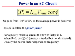
22. Power in an AC Circuit
P I V
rms rms
? cos?
?? goes from -900
to 900
, so the average power is positive)
cos(?? is called the power factor.
For a purely resistive circuit the power factor is 1.
When R=0, cos(?)=0 (energy is traded but not dissipated).
Usually the power factor depends on frequency.
23. Power in an AC Circuit
P I V
rms rms
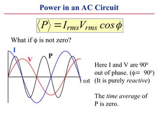
? cos?
What if ? is not zero?
I
V
P
Here I and V are 900
out of phase. (???900
)
(It is purely reactive)
The time average of
P is zero.
?t
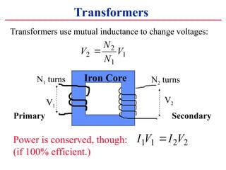
24. Transformers
Transformers use mutual inductance to change voltages:
Primary Secondary
V
N
N
V
2
2
1
1
?
N2 turns
V1
V2
N1 turns Iron Core
Power is conserved, though:
(if 100% efficient.)
I V I V
1 1 2 2
?
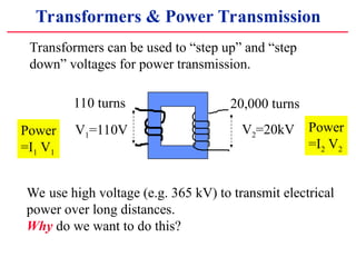
25. Transformers & Power Transmission
20,000 turns
V1=110V V2=20kV
110 turns
Transformers can be used to ˇ°step upˇ± and ˇ°step
downˇ± voltages for power transmission.
Power
=I1 V1
Power
=I2 V2
We use high voltage (e.g. 365 kV) to transmit electrical
power over long distances.
Why do we want to do this?
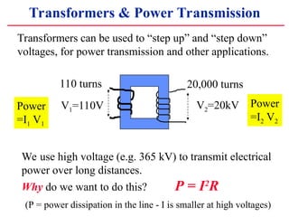
26. Transformers & Power Transmission
20,000 turns
V1=110V V2=20kV
110 turns
Transformers can be used to ˇ°step upˇ± and ˇ°step downˇ±
voltages, for power transmission and other applications.
Power
=I1 V1
Power
=I2 V2
We use high voltage (e.g. 365 kV) to transmit electrical
power over long distances.
Why do we want to do this? P = I2
R
(P = power dissipation in the line - I is smaller at high voltages)
![Phasors for a Series RLC Circuit
By PythagorasˇŻ theorem:
(VP )2
= [ (VRp )2
+ (VCp - VLp)2
]
Ip
VRp
(VCp- VLp)
VP
?
VCp
VLp](https://image.slidesharecdn.com/class16a-250407143304-dd11994f/85/class16A-pptczx-cxz-czx-cxz-zcxxxxxxxxczxczxc-9-320.jpg)
![Phasors for a Series RLC Circuit
By PythagorasˇŻ theorem:
(VP )2
= [ (VRp )2
+ (VCp - VLp)2
]
= Ip
2
R2
+ (Ip XC - Ip XL)2
Ip
VRp
(VCp- VLp)
VP
?
VCp
VLp](https://image.slidesharecdn.com/class16a-250407143304-dd11994f/85/class16A-pptczx-cxz-czx-cxz-zcxxxxxxxxczxczxc-10-320.jpg)