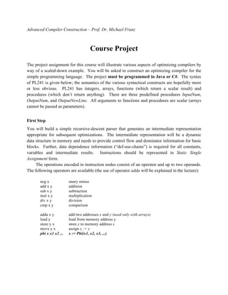
![4
EBNF for PL241
letter = ¡°a¡± | ¡°b¡± | ¡ | ¡°z¡±.
digit = ¡°0¡± | ¡°1¡± | ¡ | ¡°9¡±.
relOp = ¡°==¡° | ¡°!=¡° | ¡°<¡° | ¡°<=¡° | ¡°>¡° | ¡°>=¡°.
ident = letter {letter | digit}.
number = digit {digit}.
designator = ident{ "[" expression "]" }.
factor = designator | number | ¡°(¡° expression ¡°)¡± | funcCall .
term = factor { (¡°*¡± | ¡°/¡±) factor}.
expression = term {(¡°+¡± | ¡°-¡±) term}.
relation = expression relOp expression .
assignment = ¡°let¡± designator ¡°<-¡± expression.
funcCall = ¡°call¡± ident [ ¡°(¡° [expression { ¡°,¡± expression } ] ¡°)¡± ].
ifStatement = ¡°if¡± relation ¡°then¡± statSequence [ ¡°else¡± statSequence ] ¡°fi¡±.
whileStatement = ¡°while¡± relation ¡°do¡± StatSequence ¡°od¡±.
returnStatement = ¡°return¡± [ expression ] .
statement = assignment | funcCall | ifStatement | whileStatement | returnStatement.
statSequence = statement { ¡°;¡± statement }.
typeDecl = ¡°var¡± | ¡°array¡± ¡°[¡° number ¡°]¡± { ¡°[¡° number ¡°]¡± }.
varDecl = typeDecl indent { ¡°,¡± ident } ¡°;¡± .
funcDecl = (¡°function¡± | ¡°procedure¡±) ident [formalParam] ¡°;¡± funcBody ¡°;¡± .
formalParam = ¡°(¡° [ident { ¡°,¡± ident }] ¡°)¡± .
funcBody = { varDecl } ¡°{¡± [ statSequence ] ¡°}¡±.
computation = ¡°main¡± { varDecl } { funcDecl } ¡°{¡± statSequence ¡°}¡± ¡°.¡± .
Predefined Function
InputNum() read a number from the standard input
Predefined Procedure
OutputNum(x) write a number to the standard output
OutputNewLine() write a carriage return to the standard output](https://image.slidesharecdn.com/2017cs241project-170814051817/85/Compiler-Construction-for-DLX-Processor-4-320.jpg)
Compiler Construction for DLX Processor
- 1. Advanced Compiler Construction ¨C Prof. Dr. Michael Franz Course Project The project assignment for this course will illustrate various aspects of optimizing compilers by way of a scaled-down example. You will be asked to construct an optimizing compiler for the simple programming language. The project must be programmed in Java or C#. The syntax of PL241 is given below; the semantics of the various syntactical constructs are hopefully more or less obvious. PL241 has integers, arrays, functions (which return a scalar result) and procedures (which don¡¯t return anything). There are three predefined procedures InputNum, OutputNum, and OutputNewLine. All arguments to functions and procedures are scalar (arrays cannot be passed as parameters). First Step You will build a simple recursive-descent parser that generates an intermediate representation appropriate for subsequent optimizations. The intermediate representation will be a dynamic data structure in memory and needs to provide control flow and dominator information for basic blocks. Further, data dependence information (¡°def-use-chains¡±) is required for all constants, variables and intermediate results. Instructions should be represented in Static Single Assignment form. The operations encoded in instruction nodes consist of an operator and up to two operands. The following operators are available (the use of operator adda will be explained in the lecture): neg x unary minus add x y addition sub x y subtraction mul x y multiplication div x y division cmp x y comparison adda x y add two addresses x und y (used only with arrays) load y load from memory address y store y x store y to memory address x move y x assign x := y phi x x1 x2 ... x := Phi(x1, x2, x3, ...)
- 2. 2 end end of program bra y branch to y bne x y branch to y on x not equal beq x y branch to y on x equal ble x y branch to y on x less or equal blt x y branch to y on x less bge x y branch to y on x greater or equal bgt x y branch to y on x greater read read write x write writeNL writeNewLine The intermediate representation generated by your compiler should be visualized using the VCG (Visualization of Compiler Graphs) package that is available on the Internet (just type ¡°vcg¡± into the Google search engine). VCG is a priceless tool for debugging the kind of complex dynamic data structures that are used in optimizing compilers. Your output should consist of the CFG visually depicted by basic blocks (boxes) connected by control flow (lines), and within each basic block, the instruction list should be shown in a format similar to what we are using in class. Additionally, you should visualize the dominator tree. Second Step After you are confident that your conversion to SSA works correctly, extend your compiler by implementing common subexpression elimination and copy propagation on the control flow graph. In order to make this process visible to the user, introduce a trace mode that produces an elimination protocol. Display the resulting program after elimination in SSA form (without any MOVE instructions remaining), again using the VCG package. Perform experiments to test your implementation for correctness. Third Step Implement a global register allocator for your compiler. For this purpose, track the live ranges of all the individual values generated by the program being compiled, and build an interference graph. Color the resulting graph, assuming that the target machine has 8 general-purpose data registers. If more registers are required, map the values that cannot be accommodated onto virtual registers in memory. Eliminate all Phi-Instructions, inserting move-instructions wherever necessary. Display the final result using VCG, and perform experiments to test your implementation.
- 3. 3 Fourth Step Write a code generator for the source language that emits optimized (CSE, copy propagation, register allocation) native programs in the native load format of a real platform. You may choose your target platform from x86/Windows, x86/Linux, or you may use the DLX processor simulator. Optional Final Step Perform instruction scheduling between the register allocation and code generation stages of your compiler. Try to find a scheduling heuristic that improves performance over non-scheduled code.
- 4. 4 EBNF for PL241 letter = ¡°a¡± | ¡°b¡± | ¡ | ¡°z¡±. digit = ¡°0¡± | ¡°1¡± | ¡ | ¡°9¡±. relOp = ¡°==¡° | ¡°!=¡° | ¡°<¡° | ¡°<=¡° | ¡°>¡° | ¡°>=¡°. ident = letter {letter | digit}. number = digit {digit}. designator = ident{ "[" expression "]" }. factor = designator | number | ¡°(¡° expression ¡°)¡± | funcCall . term = factor { (¡°*¡± | ¡°/¡±) factor}. expression = term {(¡°+¡± | ¡°-¡±) term}. relation = expression relOp expression . assignment = ¡°let¡± designator ¡°<-¡± expression. funcCall = ¡°call¡± ident [ ¡°(¡° [expression { ¡°,¡± expression } ] ¡°)¡± ]. ifStatement = ¡°if¡± relation ¡°then¡± statSequence [ ¡°else¡± statSequence ] ¡°fi¡±. whileStatement = ¡°while¡± relation ¡°do¡± StatSequence ¡°od¡±. returnStatement = ¡°return¡± [ expression ] . statement = assignment | funcCall | ifStatement | whileStatement | returnStatement. statSequence = statement { ¡°;¡± statement }. typeDecl = ¡°var¡± | ¡°array¡± ¡°[¡° number ¡°]¡± { ¡°[¡° number ¡°]¡± }. varDecl = typeDecl indent { ¡°,¡± ident } ¡°;¡± . funcDecl = (¡°function¡± | ¡°procedure¡±) ident [formalParam] ¡°;¡± funcBody ¡°;¡± . formalParam = ¡°(¡° [ident { ¡°,¡± ident }] ¡°)¡± . funcBody = { varDecl } ¡°{¡± [ statSequence ] ¡°}¡±. computation = ¡°main¡± { varDecl } { funcDecl } ¡°{¡± statSequence ¡°}¡± ¡°.¡± . Predefined Function InputNum() read a number from the standard input Predefined Procedure OutputNum(x) write a number to the standard output OutputNewLine() write a carriage return to the standard output