Constantin Iancu’S Fea Skills
- 1. Constantin Iancu’s FEA skills Master of Science in Finite Element Analysis (M.Sc.) Over 10 years hands on FEA experience
- 2. Title page of Master of Science Thesis _______________________________________________________________
- 3. Title page for Post graduated Diploma ______________________________________________________________
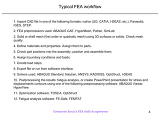
- 4. Typical FEA workflow _______________________________________________________________ 1. Import CAD file in one of the following formats: native (UG, CATIA, I-DEAS, etc.), Parasolid, IGES, STEP. 2. FEA preprocessors used: ABAQUS CAE, HyperMesh, Patran, SimLab 3. Solid or shell mesh (first order or quadratic mesh) using 3D surfaces or solids. Check mesh quality. 4. Define materials and properties. Assign them to parts. 5. Check part positions into the assembly, position and assemble them. 6. Assign boundary conditions and loads. 7. Create load steps. 8. Export file or run from software interface. 9. Solvers used: ABAQUS Standard, Nastran, ANSYS, RADIOSS, OptiStruct, I-DEAS 10. Postprocessing the results: fatigue analysis, or create PowerPoint presentation for stress and displacements contours using one of the following postprocessing software: ABAQUS Viewer, HyperView 11. Optimization software: TOSCA, OptiStruct 12. Fatigue analysis software: FE-Safe, FEMFAT
- 5. Example 1: Structural rack support _______________________________________________________________ Bolts pretensioned & contact and friction Tie connection to replace weld Rack with three levels (37,000lb per level) Constraint in all DOF (123456) Load applied as an uniform distributed pressure over the cross-members of the rack Target: verify the capability of the rack to support 37,000lb per level
- 6. Example 2: Diesel engine boost pipe _______________________________________________________________ Normal mode analysis for a Diesel engine boost pipe Contact between dummy plate – gasket (steel – rubber) and Aluminum housing Constraint in all DOF (123456) at Venturi pipe Bolts pretensioned & contact and friction Target: improve bracket geometry to raise the first and second frequency over 156 Hz Constraint in all DOF (123456) at support bracket Constraint in all DOF (123456) at the dummy plate Mixed model: first order hexahedral and tetrahedral elements
- 7. Example 3: Automatic flexplate assembly _______________________________________________________________ FEA analysis of a flexplate assembly (Powertrain – automatic transmission) Target: Analyze structural integrity of the flexplate under six different loads: axial, torsional, misalignment, centrifugal and combined loads (A-T-C, A-T-C-M) Ring gear welded at the flexplate Contact between: flexplate, lugs, reinforcements, and bolts Constraint in all DOF (123456) at crankshaft
- 8. Example 4: Support bracket optimization _______________________________________________________________ Frequency optimization of the support bracket for a Diesel engine boost pipe Target: minimize mass of the bracket that will vibrate with a frequency higher than 156Hz Design space: material to be removed Constrained: holes attachment areas Software: TOSCA
- 9. Example 5: Fatigue analysis for an axle assembly _______________________________________________________________ Run FE-Safe to get life predictions based on an ABAQUS odb file. Steps: - read ODB file - assign materials - create loading history - run FE-Safe - post-process results


