Controller Implementation in Verilog
- 1. Controller Anees Akhtar 12-ENC-20 Muhammad Nabi Yasinzai 12-ENC-36
- 2. Controller Structure Top Module ? Arithmetic Logic Unit ? Register File ? Program Memory ? Control Unit
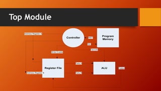
- 3. Top Module Program Memory Controller Register File ALU INST Opcode Write Enable INC Data A Address Register A Address Register B Output Data B
- 4. Top Module module Top_Module(Clk,Reset,PRO_COUNT,INSTRUCTION, AD_A, AD_B, AD_D, A_Out , B_Out,ALU_Out,W_E,OP_CODE); ? input Clk , Reset ; ? output [15:0] INSTRUCTION; ? output [3:0] PRO_COUNT; ? output [15:0] A_Out , B_Out ; ? output [2:0] AD_A, AD_B, AD_D; ? output [15:0] ALU_Out; ? output [3:0] OP_CODE; ? output W_E ;
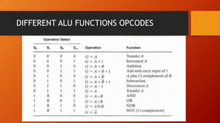
- 5. Arithmetic Logic Unit OpCode [3:0] INST[13:10] A[15:0] ALU_Out [15:0] B[15:0] ? Two 16 Bit Data inputs (Input A , Input B) ? 4 Bit OpCode(Select lines) To choose A desired Function ? In Our design we have 8 arithmetic operations & Four Logical Operations. ? One 16 bit ALU output. ? In Our Design the OpCode Holds the [13:10] bits of the instruction. module AL_Unit (OpCode , A , B , ALU_Out ) ; input [15 : 0] A , B ; input [3 : 0] OpCode ; output [15 : 0] ALU_Out ;
- 6. DIFFERENT ALU FUNCTIONS OPCODES
- 7. Register File A address A_A[2:0] iNST[4:6] ? Two Read Adresses To Read the Data From two Loctions in the registerfile ? A_Out and B_Out are the output data selected by their addresses. ? Write enable(W_E) is used to write Data on the location selected by Destination Adress(D_A). module REGISTER_FILE ( Reset , Clk , A_A , A_B , A_Out , B_Out , W_E, D_A , D_Input); input Reset, Clk; input [ 2:0] A_A, A_B; input W_E; input [ 2:0] D_A; input [15:0] D_Input; output [15:0] A_Out,B_Out; D-addres A_B[2:0] iNST[7:9] Wrie enable iNST[0] B address A_B[2:0] iNST[4:6]
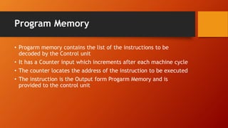
- 8. Program Memory ? Progarm memory contains the list of the instructions to be decoded by the Control unit ? It has a Counter input which increments after each machine cycle ? The counter locates the address of the instruction to be executed ? The instruction is the Output form Progarm Memory and is provided to the control unit
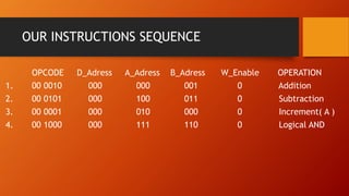
- 9. OUR INSTRUCTIONS SEQUENCE OPCODE D_Adress A_Adress B_Adress W_Enable OPERATION 1. 00 0010 000 000 001 0 Addition 2. 00 0101 000 100 011 0 Subtraction 3. 00 0001 000 010 000 0 Increment( A ) 4. 00 1000 000 111 110 0 Logical AND
- 10. Control Unit ? Contol Unit decodes the instruction From the Program Memory and Provides signals to the Other components. Its execution consists of three steps. 1. Fetching 2. Decoding 3. Loading module CONTROL(Clk,Reset,INST_IN,COUNT_ADD,AD_A,AD_B,AD_D,OP_CODE,W_E); input [15:0]INST_IN; input Clk,Reset ; output W_E; output [3:0] COUNT_ADD ; output [3:0] OP_CODE ; output [2:0] AD_A, AD_B, AD_D ;
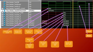
- 11. Clock Reset Counter at 0 count INSTRUCTION STORED AT 0 OPCODE FOR ADDITION Adress of A 000 Adress of B 001 Destination address 010 Data stored in register 001 Data stored in register 000 SUM OF THE INPUT DATA
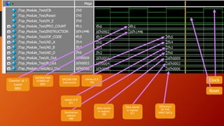
- 12. Clock Reset Counter at 1 count 0001 INSTRUCTION STORED AT 0001 OPCODE FOR Subtraction Adress of A 100 Adress of B 011 Destination address 000 Data stored in register 100 Data stored in register 011 Difference OF THE INPUT DATA
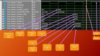
- 13. Clock Reset Counter at 2 count 0010 INSTRUCTION STORED AT 0010 OPCODE FOR Increment 0001 Adress of A 010 Adress of B 000 Destination address 000 Data stored in register A 010 Data stored in register B 000 INREMENTED RESULT


![Top Module
module Top_Module(Clk,Reset,PRO_COUNT,INSTRUCTION, AD_A, AD_B, AD_D, A_Out , B_Out,ALU_Out,W_E,OP_CODE);
? input Clk , Reset ;
? output [15:0] INSTRUCTION;
? output [3:0] PRO_COUNT;
? output [15:0] A_Out , B_Out ;
? output [2:0] AD_A, AD_B, AD_D;
? output [15:0] ALU_Out;
? output [3:0] OP_CODE;
? output W_E ;](https://image.slidesharecdn.com/projectpresentation-150201054124-conversion-gate02/85/Controller-Implementation-in-Verilog-4-320.jpg)
![Arithmetic Logic Unit
OpCode [3:0] INST[13:10]
A[15:0]
ALU_Out
[15:0]
B[15:0]
? Two 16 Bit Data inputs (Input A , Input B)
? 4 Bit OpCode(Select lines) To choose A desired Function
? In Our design we have 8 arithmetic operations
& Four Logical Operations.
? One 16 bit ALU output.
? In Our Design the OpCode Holds the [13:10] bits of the instruction.
module AL_Unit (OpCode , A , B , ALU_Out ) ;
input [15 : 0] A , B ;
input [3 : 0] OpCode ;
output [15 : 0] ALU_Out ;](https://image.slidesharecdn.com/projectpresentation-150201054124-conversion-gate02/85/Controller-Implementation-in-Verilog-5-320.jpg)
![Register File
A address
A_A[2:0]
iNST[4:6]
? Two Read Adresses To Read the Data From two Loctions in the registerfile
? A_Out and B_Out are the output data selected by their addresses.
? Write enable(W_E) is used to write Data on the location selected by
Destination Adress(D_A).
module REGISTER_FILE ( Reset , Clk , A_A , A_B , A_Out , B_Out , W_E, D_A , D_Input);
input Reset, Clk;
input [ 2:0] A_A, A_B;
input W_E;
input [ 2:0] D_A;
input [15:0] D_Input;
output [15:0] A_Out,B_Out;
D-addres
A_B[2:0]
iNST[7:9]
Wrie
enable
iNST[0]
B address
A_B[2:0]
iNST[4:6]](https://image.slidesharecdn.com/projectpresentation-150201054124-conversion-gate02/85/Controller-Implementation-in-Verilog-7-320.jpg)
![Control Unit
? Contol Unit decodes the instruction From the Program Memory and Provides signals to the Other
components.
Its execution consists of three steps.
1. Fetching
2. Decoding
3. Loading
module CONTROL(Clk,Reset,INST_IN,COUNT_ADD,AD_A,AD_B,AD_D,OP_CODE,W_E);
input [15:0]INST_IN;
input Clk,Reset ;
output W_E;
output [3:0] COUNT_ADD ;
output [3:0] OP_CODE ;
output [2:0] AD_A, AD_B, AD_D ;](https://image.slidesharecdn.com/projectpresentation-150201054124-conversion-gate02/85/Controller-Implementation-in-Verilog-10-320.jpg)
