Couplings : Types & Applications
- 1. COUPLING
- 2. WHAT IS COUPLING ? A device that is used to connect two shafts(Input Shaft & Output Shaft / driving shaft & driven shaft) together for the purpose of power transmission.
- 3. WHY DO WE NEED COUPLINGS ? Power can be transmitted by means of various gear arrangements or drives only if the shafts are parallel. Couplings are used when the shafts are in a straight line and are to be connected end to end to transmit power.
- 4. PURPOSE OF COUPLING ? 1. Power Transmission 2. Joining misalignment of shafts 3. Reduce shock violation 4.Easy to assemble and disassemble
- 5. TYPES OF COUPLING ? ŌĆó General types of couplings are: ŌĆōrigid: for aligned shafts ŌĆōflexible: for non-aligned shafts
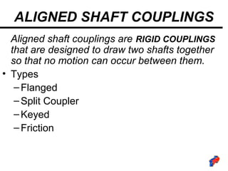
- 6. ALIGNED SHAFT COUPLINGS Aligned shaft couplings are RIGID COUPLINGS that are designed to draw two shafts together so that no motion can occur between them. ŌĆó Types ŌĆōFlanged ŌĆōSplit Coupler ŌĆōKeyed ŌĆōFriction
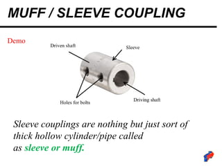
- 7. MUFF / SLEEVE COUPLING Sleeve couplings are nothing but just sort of thick hollow cylinder/pipe called as sleeve┬Āor┬Āmuff. Demo
- 8. MUFF / SLEEVE COUPLING The sleeve is manufactured keeping the diameter of shaft in mind so that the shaft fits perfectly into the sleeve. The driver & driven, both the shafts are then inserted into each side of the sleeve. Also two or more threaded holes are provided into the sleeve as well as in both of the shaftŌĆÖs end so that they donŌĆÖt move in longitudnal direction Also the keyway and key ensures that the shaft and sleeve doesnŌĆÖt slip.
- 9. SPLIT MUFF / CLAMP COUPLING In split muff coupling, the sleeve or muff isnŌĆÖt a single different part instead it is split into 2
- 10. SPLIT MUFF / CLAMP COUPLING In split muff coupling, the sleeve or muff isnŌĆÖt a single different part instead it is split into 2 The muffs are semi-cylindrical in shape which then fits over the shaft. Threaded holes are provided on the muffs so that both the shafts can be joined with steel bolts or studs. The special feature of this coupling is that it can be assembled and disassembled without changing the position of shaft. Application- They are used for medium to heavy duty load with moderate speed.
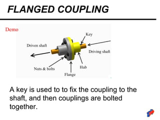
- 11. FLANGED COUPLING A key is used to to fix the coupling to the shaft, and then couplings are bolted together. Demo
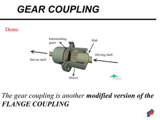
- 12. GEAR COUPLING The gear coupling is another modified version of the FLANGE COUPLING Demo
- 13. GEAR COUPLING In gear coupling, the flange and hub are different parts assembled together instead of a single part as in flange coupling. The hubs are externally splined but they are so thick and deep that you can regard them as gear teeth. Also the flanges have internal teeth. The gear ratio is 1:1 and are meshed together. The single joint gear couplings are limited to lower angular misalignments. Application- Gear couplings are used for heavy-duty applications where requirement of torque transmission is higher.
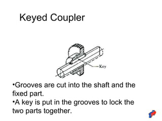
- 14. Keyed Coupler ŌĆóGrooves are cut into the shaft and the fixed part. ŌĆóA key is put in the grooves to lock the two parts together.
- 15. Friction Coupling Clutch Disengaged Clutch Engaged Driver Plate A Friction Material Driven Shaft Stationary Driver Shaft In motion Driver Shaft In motion Driven Shaft In motion
- 16. NON-ALIGNED SHAFT COUPLINGS ŌĆó Used to join SHAFTS THAT MEET AT A SLIGHT ANGLE / INTERSECTING SHAFTS ŌĆó Angle may still change while running due to vibration or load. ŌĆó Types: ŌĆōUniversal ŌĆōConstant Velocity ŌĆōFlexible
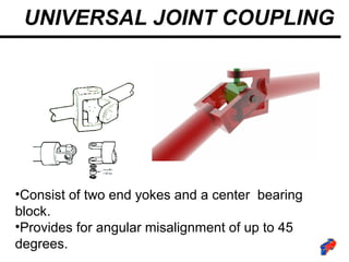
- 17. UNIVERSAL JOINT COUPLING ŌĆóConsist of two end yokes and a center bearing block. ŌĆóProvides for angular misalignment of up to 45 degrees.
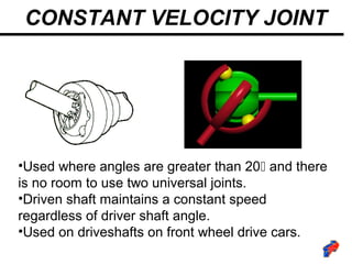
- 18. CONSTANT VELOCITY JOINT ŌĆóUsed where angles are greater than 20’é░ and there is no room to use two universal joints. ŌĆóDriven shaft maintains a constant speed regardless of driver shaft angle. ŌĆóUsed on driveshafts on front wheel drive cars.
- 19. FLEXIBLE COUPLING Where shafts cant be aligned properly Best for ŌĆóPower Transmission Limitation ŌĆóCostly / complex construction
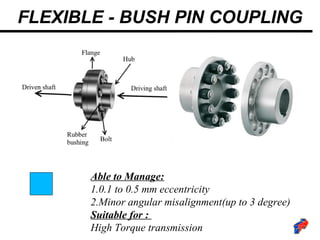
- 20. FLEXIBLE - BUSH PIN COUPLING Able to Manage: 1.0.1 to 0.5 mm eccentricity 2.Minor angular misalignment(up to 3 degree) Suitable for : High Torque transmission
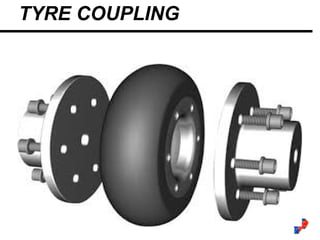
- 21. TYRE COUPLING
- 22. ŌŚÅ Acts as Self-Aligning Agent ŌŚÅ Avoids Metal Contact ŌŚÅ Smoothness Vibration ŌŚÅ Gives Life to Bearings ŌŚÅ Removes Unpleasant Sound ŌŚÅ Takes End Level Shock Load ŌŚÅ Makes Easy Replacement ŌŚÅ Suits to Vertical Drive ŌŚÅ Avoids Cost Against Breakdown ŌŚÅ Decreases Temperature Rise TYRE COUPLING
- 23. JAW & SPIDER COUPLING
- 24. JAW & SPIDER COUPLING Their application is ideal for transmitting torque while damping torsional vibrations and absorbing shocks produced by the uneven operation of certain prime movers torsionally flexible and designed for positive torque transmission. They are failsafe. Operational vibrations and shocks are efficiently dampened and reduced
- 25. FLUID COUPLING
- 26. FLUID COUPLING Fluid coupling consists of 2 parts ŌĆō a pump & a turbine. Both of these have blades mounted inside at a certain angle. The pump is mounted on the end of driver shaft while the turbine on the driven shaft. The fluid enters into the pump through its centre and when the driver shaft rotates, due to centrifugal force it is pushed outwards. The casing is such that it diverts the motion of fluid into the turbine and the turbine blades along with turbine starts rotating. This way the pump and the turbine both make a coupling. When an extra part called a reactor is introduced between the pump and the turbine, surprisingly the device becomes a torque converter which is an alternative to manual clutch in automatic transmission systems in cars !
- 27. FLUID COUPLING Application- It is widely used in marine and industrial applications where controlled start-up of the power transmission is very essential.
- 28. BELLOWS COUPLING
- 29. BELLOWS COUPLING Bellows couplings are an assembly of two aluminum hubs and a uniform, thin walled stainless steel bellows. The use of aluminum hubs with a bellows results in a coupling with very low inertia, The characteristics of bellows make them an ideal method for transmitting torque in motion control applications. The bellows allow the coupling to bend easily under loads caused by the three basic types of misalignment between shafts (angular, parallel, axial motion).
- 30. BIBBY COUPLING
- 31. BIBBY COUPLING Applications : Cement Mills ŌĆō in grinding and crushing machinery. Cranes Conveyors Turbines Marine Auxiliaries Paper Mills
- 32. COUPLINGS ŌĆō PARALLEL SHAFT ŌĆó Used to join PARALLELSHAFTS ŌĆó Case of eccentricity in Rotating shafts
- 33. OLDHAMŌĆÖs COUPLINGS ŌĆó Used to join PARALLELSHAFTS ŌĆó Case of eccentricity in Rotating shafts Driving Tongue Driven


