Declaration
- 1. i Dedication This project is dedicated to my father, who has worked very hard to get me where I am today, who taught me that the one can start from scratch, yet accomplish great things as if he had all the abilities in the world. It is also dedicated to my mother, who stood by me all through hard times, always encouraging me, and always believing in me, she is the light of my life, the hope of my dreams. To both, I dedicate this work hoping it will make them proud of me.
- 2. ii ACKNOWLEDGEMENT We would like to sincerely thank our supervisor Dr. Kamal Altayeb for all his help, support and patience throughout this project. We would also like to thank all the lecturing staff of the University of Khartoum for the past five years of guidance. We would especially like to thank our parents and family for their love and encouragement. Thank you, finally, to all our friends for their backing and friendship over the years.
- 3. iii âŦاŲŲ ØģØŠØŪŲâŽâŦØĩ⎠âŦاŲŲ؊ا؎⎠âŦŲ ØĩŲØđ⎠âŦØŠØĩŲ ŲŲ ⎠âŦØŠŲ âŽ022âŦاŲØاØĶط⎠âŦØģŲØąØ§Ų ŲŲ⎠âŦŲ Ų⎠âŦØ·Ų/اŲŲŲŲ âŽØâŦاŲŲاŲŲŲŲ⎠,âŦاŲŲŲØģØĻØ§ØąâŽ ,âŦاŲØģŲŲŲŲا⎠,âŦاŲØ·ŲŲ⎠âŦŲ Ų⎠âŦاŲŲ ŲŲŲ⎠âŦاŲطاŲØĐ⎠âŦŲ⎠âŦاŲŲØŠŲØĐ⎠âŦØŲØļ⎠âŦŲ ØđاØŊاŲ؊⎠âŦاŲØđŲ Ų⎠âŦŲذا⎠âŦØŠØķŲ Ų⎠âŦØŲØŦ⎠.âŦØĻŲ؎اØ⎠âŦØĢŲŲŲØĐ⎠âŦŲŲ ŲاØŊ⎠)âŦ(اŲŲŲØģØĻØ§ØąâŽ âŦاŲØŽŲØąŲ⎠âŦاŲØØŽØąâŽ âŦŲ⎠âŦØŠØĩŲ ŲŲ ⎠âŦŲ⎠,âŦاŲØŠØŊŲŲ⎠âŦŲ ØŪطط⎠,âŦاŲŲ ØĩŲØđ⎠âŦØŠŲØģŲŲ⎠,âŦاŲØĻŲØ§ØĄâŽ âŦŲ ŲاØŊ⎠,âŦاŲØŠØŲŲ ⎠âŦŲ⎠âŦاŲŲ ØđØŊا؊⎠âŦ,اØģØŠØąØ§ØŠŲØŽŲا؊⎠âŦŲاŲ Ų⎠âŦŲŲŲ ØĩŲØđ⎠âŦاŲ؊⎠âŦŲ ØŪطط⎠.âŦاŲŲØĻŲØąØĐ⎠âŦاØĢŲØŽŲØēØĐâŽâŦاŲØđŲ Ų⎠âŦاØŪ؊؊Ų ⎠.âŦاŲŲ ŲاØŊ⎠âŦØŠØŊŲŲ⎠âŦŲ⎠âŦØŠØīØšŲŲŲا⎠âŦØاŲØĐ⎠âŦŲ⎠âŦاØĢŲØģاØģŲØĐ⎠âŦاØĢŲØŽŲØēØĐ⎠âŦŲ ØŠØķŲ Ųا⎠âŦØŽØ§ØĄâŽ âŦØŊŲŲ⎠âŦŲ⎠ØâŦاŲŲ ØŽŲŲ⎠ØâŦاŲŲŲØŊØąŲŲŲŲŲ⎠âŦاŲØķاؚط⎠ØâŦاŲØąØī⎠âŦŲ ØŽŲŲ⎠ØâŦاŲŲØąØ§ØŠâŽ âŦŲ Ø·ØŲØĐ⎠ØâŦاŲØŪØēاŲ⎠:âŦØīŲ Ų⎠âŦاŲØ°Ų⎠âŦااŲŲØŠØĩاØŊŲ⎠âŦØĻاŲØŠŲŲŲŲ ⎠.âŦŲŲØĻŲØ§ØĄâŽ âŦاŲŲŲŲØĐ⎠âŦŲŲØŠŲŲŲØĐ⎠âŦاŲØŠŲŲŲŲ ⎠âŦØŦŲ ⎠,âŦاŲŲØąŲ⎠âŦŲØŠØ⎠âŦŲ ØŠŲاŲ Ų⎠âŦØģŲØąØ§Ų ŲŲ⎠âŦŲ ØĩŲØđ⎠âŦاŲ؊ا؎⎠âŦŲŲ⎠âŦاŲŲ ØīØąŲØđ⎠âŦŲ Ų⎠âŦاŲŲØŊŲâŽâŦاŲØŠØĩØŊŲØąâŽ âŦØ°ŲŲ⎠âŦØĻØđØŊ⎠âŦØŦŲ ⎠âŦŲŲØģŲØŊاŲ⎠âŦاŲذا؊Ų⎠âŦااŲŲØŠŲØ§ØĄâŽ âŦŲŲŲ⎠.âŦاŲŲ ؎اŲØąØĐ⎠âŦŲŲØŊŲŲ⎠âŦŲاŲ؊⎠âŦŲŲŲ ØĩŲØđ⎠âŦاØĢŲŲŲŲØĐ⎠âŦاŲØŠŲŲŲØĐ⎠âŦØĢŲ⎠âŦŲØŽØŊ⎠âŦاŲØđŲ Ų⎠âŦŲŲاŲØĐ⎠âŦŲŲâŽ9âŦØŠŲØŊØąâŽ âŦاŲØĩŲاŲØĐ⎠âŦŲ⎠âŦŲŲØŠØīØšŲŲ⎠âŦØģŲŲŲØĐ⎠âŦØŠŲŲŲØĐ⎠âŦŲ Øđ⎠âŦØŊŲاŲØąâŽ âŦŲ ŲŲŲŲ⎠âŦØĻŲâŽ15.6.âŦØĻŲØģŲØŠŲŲ⎠âŦŲØŊØąØŠâŽ âŦاŲŲ ØīØąŲØđ⎠âŦŲØŠŲŲŲذ⎠âŦاŲØēŲ ŲŲØĐ⎠âŦاŲØŪØ·ØĐ⎠.âŦØŊŲاŲØąâŽ âŦŲ ŲŲŲŲâŽ
- 4. iv Abstract The design of a plant for the production of 200 ton/day wall tile ceramics from clays, kaolin, feldspar, silica, and calcite has been successfully carried out. The various process routes were examined through which production was employed. The work covered material and energy balances for the entire process. The process flowsheet shows major items of equipment, their operating conditions and material flows. Moreover the work also covered the instrumentation and control strategies for the process, the material for construction, plant layout, process flow sheet, and associated equipment design. The economic evaluation of the major equipment to include: storage tank, ball mill, spray dryer, hydraulic press, dryer, and a tunnel kiln. Its objective is to produce an economically feasible ceramic plant to cover local requirements and export the rest to nearby countries. The capital cost for the preliminary design is estimated at $9M with annual O&M )operations &Maintenance) costs of $15.6 M. The project implementation and construction is expected to last 24 months.
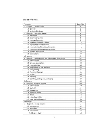
- 5. v List of contents: Contents Page No. 1. Chapter 1_ introduction 1 1.1. general 2 1.2. project objectives 3 2. chapter 2_ literature review 4 2.1. definition 5 2.2. ceramic properties 6 2.3. history of ceramic 8 2.4. types of traditional ceramic 14 2.5. types of advanced ceramic 15 2.6. raw material of traditional ceramics 16 2.7. raw material of advanced ceramics 21 2.8. process description 23 2.9. applications 37 references 41 3. chapter 3_ unglazed wall and tiles process description 42 3.1. introduction 43 3.2. process description 44 3.3. raw materials 44 3.4. preparation of raw materials 44 3.5. spray drying 46 3.6. forming (shaping) 46 3.7. drying 46 3.8. sintering 46 3.9. polishing, sorting and packaging 47 References 48 4. chapter 4_material balance 49 4.1. introduction 50 4.2. ball mill 51 4.3. spray dryer 52 4.4. hydraulic press 53 4.5. dryer 54 4.6. roller hearth kiln 55 4.7. total material balance 59 references 60 5. chapter 5_ energy balance 61 5.1. introduction 62 5.2. equations 62 5.3. calculations 64 5.3.1.spray dryer 64
- 6. vi 5.3.2.dryer 67 5.3.3.roller hearth kiln 69 5.4. total heat balance (before the kiln) 75 References 78 6. chapter 6_equipment design 79 6.1. ball mill 80 6.1.1.grinding general review 80 6.1.2.design options 80 6.1.3.general description of ball mill 84 6.1.4.bondâs method 85 6.1.5.Denverâs model 89 6.1.6.Other variables 90 6.1.7.Variables determination 91 6.1.8. Calculations 92 6.1.9.summary 95 References 97 6.2. spray dryer 98 6.2.1.evaporation rate 98 6.2.2.prediction of mean diameter 98 6.2.3.the efficiency 102 6.2.4.wheel atomizer 102 6.2.5.chamber design 106 6.2.6. air droplet contact system 108 6.2.7.Powder and air discharge system 110 6.2.8.Material of construction 111 References 112 6.3. Hydraulic press design 113 6.3.1.Hydraulic cylinder construction 114 6.3.2.Calculations 117 References 121 6.4. Tunnel dryer 122 6.4.1.Selection of type 123 6.4.2.Design calculation 124 References 127 6.5. Kiln 128 6.5.1.introduction 128 6.5.2. choosing the type of kiln 130 6.5.3.Roller hearth kiln 130 6.5.4.Reactions in the kiln 133 6.5.5.design 136 6.5.6.parameters selection 140 References 143
- 7. vii 7. chapter 7 Ancillaries design 144 7.1. storage tanks 145 7.1.1.liquid (slurry) storage tank 145 7.1.2.powder storage tank 148 7.2. ball mill classifier 148 7.3. spray dryer pump(101) 151 7.4. air heater 151 7.5. spray dryer fan 153 7.6. spray dryer cyclone 154 References 156 8. chapter 8_process control 157 8.1. ball mill control 158 8.1.1.process model 158 8.1.2.PI controller design 161 8.1.3.Detuned multi-loop PID control 163 8.2. Control of spray dryer 165 8.2.1.PI controller 167 8.2.2.PI controller for disturbance rejection of solids content variation 167 8.3. Control of hydraulic press 168 8.3.1.Model estimation 170 8.3.2.Self-tuning fuzzy PID controller design 170 8.4. Roller hearth kiln control 174 8.4.1.Proportional control 175 8.4.2.PID controller 177 8.4.3.Design of PID controller 180 References 184 9. Chapter 9_ safety and environmental consideration 185 9.1. Introduction 186 9.2. Environmental considerations 186 9.2.1.air emissions 186 9.2.2.waste water 195 9.2.3.solid waste 198 9.3. health and safety issues 199 9.3.1.respiratory hazards 199 9.3.2.exposure to heat 203 9.3.3.noise and vibration 203 9.3.4.physical hazards 204 9.3.5.Electrical hazards 204 References 205 10. Plant location and layout 206 10.1. Plant location 207
- 8. viii 10.2. Plant layout 208 10.2.1. Detailed analysis of the production 210 10.2.2. planning 212 10.2.3. the final layout 213 References 215 11. economic evaluation 216 11.1. introduction 217 11.2. capital investment 218 11.2.1. fixed capital investment 221 11.2.2. working capital investment 227 11.3. total product cost 228 11.3.1. manufacturing costs 229 11.3.2. general expenses 233 11.4. sensitivity analysis 235 11.4.1. project evaluation 236 References 240 12. project recommendations 241 12.1. recommendations 242 Appendix: Questionnaire to Salomy Italy 243
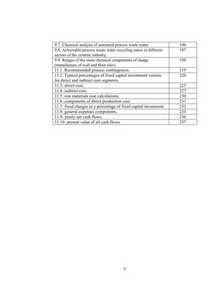
- 9. ix List of tables: Table content Page number 4.1. Inlet raw materials to the plant 50 4.2. Inlet material to the ball mill 51 4.3. Outlet materials from the spray dryer to the hydraulic press 52 4.4. Outlet water vapour from spray dryer to exhaust 52 4.5. Inlet materials to the hydraulic press 52 4.6. Outlet materials from the hydraulic press to the dryer 53 4.7. Materials lost in pressing process 54 4.8. Outlet materials from the dryer to the kiln 54 4.10 Inlet materials to the kiln 55 4.11. Reactions in the kiln 55 4.12. Reactions in the kiln continuous 58 4.13. Materials existing the kiln 58 4.14. total material balance 59 6.1. The characteristics of the mill and test conditions 86 6.2. The results of the standard Bondâs grind ability test 87 6.3. Calculation of solid density 93 6.4. Summary of ball mill design 95 6.5. Diameter of droplets versus number of droplets 98 6.6. Materials of construction of hydraulic cylinder 114 7.1. nominal capacities of standard vertical cylindrical tanks 147 7.2. selection summary of spray dryer pump 151 7.3. design summary of air heater 152 7.4. design summary of spray dryer fan 153 7.5. selection summary of spray dryer cyclone 155 8.1. paired controlled variables with manipulated variables in ball mill control system 162 8.2. Effect of increasing P, I, and D gains on dynamic characteristics 179 8.3. tuning formulas for PID controller design in Ziegler-Nichols method 181 8.4. The parameter gain values obtained for different PID controllers for kiln. 181 9.1. Operating data and raw gas values of spray drying unit 187 9.2. emission components data and raw gas values of spray drying unit 187 9.3. Operating data and raw gas values of dryers 188 9.4. emission components data and raw gas values of dryers 188 9.5. Operating data and raw gas values in firing 189 9.6. emission components data and raw gas values in firing 189
- 10. x 9.7. Chemical analysis of untreated process waste water 196 9.8. Achievable process waste water recycling ratios in different sectors of the ceramic industry. 197 9.9. Ranges of the main chemical components of sludge (manufacture of wall and floor tiles). 198 11.1. Recommended process contingences. 219 11.2. Typical percentages of fixed capital investment various for direct and indirect cost segments. 220 11.3: direct cost. 225 11.4: indirect cost. 227 11.5: raw materials cost calculations. 230 11.6: components of direct production cost. 231 11.7: fixed charges as a percentage of fixed capital investment. 232 11.8: general expenses components. 235 11.9: yearly net cash flows. 236 11.10: present value of all cash flows. 237
- 11. xi List of figures: Figure content Page number 6.1. General description of ball mill 84 6.2. Description of wet ball mill 85 6.3. Final sketch of the ball mill showing design specifications 96 6.4. lognormal distribution in probability paper 100 6.5. Rosin- Rambler distribution on log-log paper 101 6.6. Wheel atomizer with straight radial vans 103 6.7. Peripheral velocity atomizer as a function of the wheel diameter and revolutions 104 6.8. spray dried powder 106 6.9. Height H of the drying chamber versus diameter d 107 6.10. spray dryer layout 108 6.11. drying chamber layouts 109 6.12. hot air distribution layout 109 6.13. Temperature and vapour pressure profiles along the drying chamber 110 6.14. Possible areas of impingement on the drying chamber wall 110 6.15. Discharge systems A, outlet air, DP, dry product, V, vibrator 111 6.16. hydraulic press 113 6.17. cylinder construction of hydraulic press 114 6.18. Configuration of typical tunnel dryers 123 6.19. Model of hot air counter-current flow for design of continuous tunnel dryer 124 6.20. cross section of roller hearth kiln 133 6.21. Mullite and kaolin conversion with respect to temperature 140 6.22. ranges of industrial maturing temperatures for different product groups 141 7.1. fixed roof storage tank 146 7.2. determination of dâ â from desired particle separation 149 7.3. Chamber diameter, DË from flow rate, physical properties and dâ â 150 7.4. centrifugal fan 153 7.5. dry cyclone design 154 7.6. Cyclone efficiency curves, theoretical and actual 155 8.1. simplest case of closed circuit system 158 8.2. ball mill feedback control loop 159 8.3. ball mill grinding circuit represents an interconnected multivariable system with strong interactions 159 8.4. Schematic diagram of a two-input two-output ball mill control system. 162
- 12. xii 8.5. two control loops and decouplers in ball mill control system 164 8.6. Illustration of the process input and outputs to the spray drying system and disturbances which can be used in the controller design process. 165 8.7. Illustration of feed rate control by using a PI controller for spray dryer 166 8.8. The temperature control system by feed rate variation for spray dryer 168 8.9. Electro-hydraulic actuator 169 8.10. Structure of self-tuning fuzzy PID controller for hydraulic press 171 8.11. Fuzzy inference block for hydraulic press control system 172 8.12. Simulink Block of Fuzzy PID regulator for hydraulic press 173 8.13. Simulink Block of the system and controller for hydraulic press 173 8.14. Closed-loop temperature control feedback system for kiln 175 8.15. closed-loop temperature control system for kiln 178 8.16. PID temperature controller for kiln 179 8.17. The step response of the variable (y) under PID control 182 9.1. Schematic view of a bag filter with pressure pulse regeneration 191
- 13. xiii Chapter revisions Chapter 1: it includes an introduction about industrial issues and development problems solved by ceramics materials and a brief history of ceramic production, also includes the project objectives. Chapter 2: it presents a complete definition of ceramic, its types and properties, a historical view and its various raw materials for various types. With the emphasis on the basic raw materials such as clays, feldspar and their combination, ratios, characteristics, presence, and use. Then a general process description for all types that only differ in raw materials but have the same production process, a survey of each step is presented and the many alternatives it can be done by. Finally the applications of ceramics materials are mentioned briefly. Chapter 3: in this chapter the chosen process for the chosen ceramic type (unglazed wall and floor tiles) is presented. Raw materials are defined and their proper ratios, choices of alternatives are also defined. Heating methods, cooling methods, and equipmentused are determined. Chapter 4: Material balance The total amount of the stream inlet to the ball mill contains the same flow rates of raw material (214566.7536 kg/day) but with addition of 35% water, no losses during the process. In spray dryer the water is vaporized and only 5% is left in the powder. There is 1% losses after the spray dryer and another 1% losses during the pressing process. This loss is taken from both water and ceramic materials, so the percentage of each material in the stream is maintained constant. In the dryer the amount of water is reduced to 0.3%. Chapter 5: energy balance In the spray dryer the slurry is converted to powder by evaporating the water to 5% content using hot air. Thermal efficiency is taken as 45%. In the dryer the temperature is as high as 300°C and only 0.3% water is left in the tiles, thermal efficiency is taken as 60%.
- 14. xiv In the kiln the tiles are heated up to 1190°C where several reactions occur resulting in a finished product, water vapor, and gases, tiles are cooled by air to 100 °C ,and thermal efficiency is taken as 78%. Chapter 6: equipment design It includes detailed design of several equipments in ceramic tile manufacture; ball mill, spray dryer, hydraulic press and dryer, also include proper selection of kiln and design as a reactor. Chapter 7: ancillaries design Includes completed design for storage tanks and ball mill classifier, also include proper selection for spray dryer pump, air heater, spray dryer fan, spray dryer cyclone; which satisfy our production process specification. Chapter 8: process control Presents detailed control for much equipment in plant, using PI and decentralized PID controller for ball mill, PI controller for spray dryer, self tuning fuzzy PID controller design for hydraulic press and PID controller for kiln. Chapter 9: safety and environmental considerations First the chapter deals with the environmental considerations of the ceramic production such as: air emissions, waste water, and solid waste, and presents several actions to manage these risks. Then it deals with the health and safety issues that are divided to: respiratory hazards that include exposure to silica that causes Silicosis disease, exposure to heat, noise and vibration, physical hazards, and finally electrical hazards. Chapter 10: plant location and layout Location of plant had been chosen taking many factors into account such as market and transportations, Climate Raw materials, Labor supply, water supply and energy availability and waste disposal and legal restrictions. With making tradeoff between many sites depending in several considerations; had been found that the best location is Jabal Almrkheyat western Umdurmman.
- 15. xv Plant layout had been designed including arrangement of processing areas, storage areas, and handling areas in efficient coordination and with regard to many factors that make the layout proper as possible. Chapter 11: economic evaluation This chapter evaluates our project from an economic point of view, the direct and indirect costs are calculated to obtain the fixed capital investment, the working capital is taken as a percentage of the fixed capital, and adding these two yields the total capital investment. Now the total product cost is divided into manufacturing costs and general expenses, finally the net present worth, internal rate of return, and the probability index all indicate that the project is acceptable.


