Decoder
- 1. Welcome to our presentation DECODER By Pradipta
- 2. WHAT IS DECODER ? A decoder is a logic circuit that accepts a set of inputs that represents a binary number and activates only the output the corresponds to the input number.
- 3. BASIC OF DECODER Decoders are circuits with two or more inputs and one or more outputs, resulting by combining various types of gates. Their basic function is to accept a binary word (code) as an input and create a different binary word as an output . A decoder is a device which does the reverse operation of an encoder, Lets say we have N inputs to a decoder, the number of outputs will be equal to 2^N. Thus there will be one line at the output for each possible input.
- 4. How can we use them ? Decoders are simply a collection of logic gates which are arranged in a specific way so as to breakdown any combination of inputs to a set of terms that are all set to '0' apart from one term. Therefore when one input changes, two output terms will change.
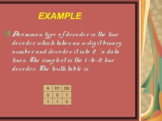
- 5. EXAMPLE A commo n type o f de co de r is the line de co de r which take s an n-dig it binary numbe r and de co de s it into 2 n data line s. The simple st is the 1 -to -2 line de co de r. The truth table is A D1 D0 0 0 1 1 1 0
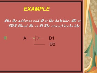
- 6. EXAMPLE A is the addre ss and D is the dataline . D0 is NOT A and D1 is A. The circuit lo o ks like A D1 D0
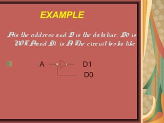
- 7. EXAMPLE A is the addre ss and D is the dataline . D0 is NOT A and D1 is A. The circuit lo o ks like A D1 D0


