Defect analysis in molded plastic part
- 1. FEA stress analysis defect in a Molded Plastic part Solidworks Simulation 8/25/2016 Don Blanchet 3B Associates dwb3298@verizon.net Model from Grabcad
- 2. CAUTION ïź Donât assume that a defect will always result in a part failure at the location of the defect. ïź Engineering experience and judgement can mislead. ïź Complex parts often have complex load paths.
- 3. PROBLEM ïź A high volume molded plastic part underwent post NC machining which introduced a defect due to an error. ïź What impact does this false cut have on the strength and factor of safety in the part. ïź Worst case Static Loading was specified by the customer.
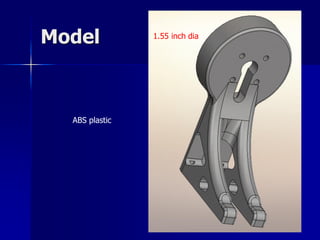
- 4. Model ABS plastic 1.55 inch dia
- 5. Model with defect NC false cut Manufacturing engineering âpart will be o.k. â ship 5,000 partsâ
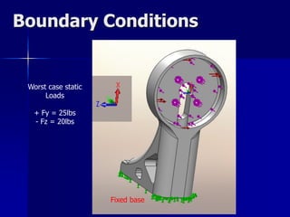
- 6. Boundary Conditions Fixed base Worst case static Loads + Fy = 25lbs - Fz = 20lbs
- 8. Stress results original design Max VonMises stress = 3,000 psi Elastic deformation
- 9. Stress results flawed part VonMises stress = 2,000 psi In flaw
- 10. Stress results flawed part Max VonMises stress = 6,000 psi Same location as original part Permanent plastic deformation here
- 11. Results Analysis case Maximum Stress psi Factor of Safety Tensile strength = 4500 psi Original 3,000 1.5 With NC Manufacturing flaw 6,000 0.75 failure
- 12. Conclusion ïź There is a significant risk in shipment of the defective parts. ïź The potential failure location is not at the defect. (surprise ! ??) ïź FEA could save the company embarrassment time and money.
- 13. Postscript ïź I started structural analysis in 1967 right out of undergrad school with the help of a slide rule and great mentors. ïź I was lucky enough to be among the earliest adopters of the finite element method. ïź It continues to please and amaze.


