Deformity correction
- 2. • Line between the center of the femoral head and the center of the knee joint (between both femoral condyles).
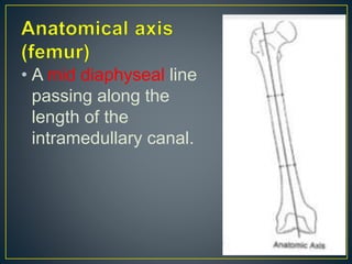
- 3. • A mid diaphyseal line passing along the length of the intramedullary canal.
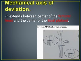
- 4. - It extends between center of the femoral head and the center of the tibial plafond.
- 6. - Lines represent the orientation of the joint in certain plane. - Knee Joint - Along the subchondral line of the tibial plateau. - Line tangential to the most distal point of the femoral condyles.
- 7. Normally joint lines are parallel within 2 degrees. Angles greater than 2 degrees are considered as a source of mechanical axis deviation (MAD).
- 8. -Angle between: -Line along the mechanical axis of the femur and line along the distal point of the femoral condyles - Normal range is 85- 90 degrees.
- 9. -Angle between: -Line along the mechanical axis of the tibia and line along the tibial plateau. - Normal range is 85- 90 degrees.
- 11. In cases of deformity:- - Angle between the distal tibial mechanical axis and line along the tibial plafond. - If one side is normal then it is used as a template for the deformed site. - If both are deformed then consider normal angles.
- 12. - (Center of rotation angle). - Point at which proximal and distal axis lines intersect. - Osteotomy fracture is done at CORA site.
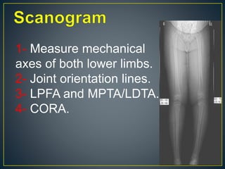
- 14. 1- Measure mechanical axes of both lower limbs. 2- Joint orientation lines. 3- LPFA and MPTA/LDTA. 4- CORA.
- 16. •THANK YOU


