Design and working of SkyTem
ŌĆóDownload as PPTX, PDFŌĆó
0 likesŌĆó1,339 views

The document describes the design and operation of the SkyTEM airborne electromagnetic system for mapping groundwater aquifers. SkyTEM uses a helicopter to carry a transmitter and receiver coil that emit electromagnetic signals to map subsurface resistivity variations. It can map to depths of 80-150m and resolve thin layers. The transmitter is a 12.5m square loop that transmits low and high moments. Over 1000 signals are averaged into each sounding. The system flies at 15-20m altitude at 15-20km/hr to map buried aquifers like those found in a 40km2 survey area in Denmark.


Design and working of SkyTem
- 1. Design and Working of SkyTEM Airborne Electromagnetic Mapping of Groundwater Aquifers Abhinav Kumar Singh, IMT-GPT IV Year, 09411002
- 2. History of Airborne Electromagnetic Systems ’üČ Airborne electromagnetic (AEM) systems have been in use for over 50 years. ’üČ The first attempts in the 1950s were quite successful in base-metal exploration in Canada, and in that decade over 10 systems were in the air. ’üČ With the decline in exploration for base metals, the use of AEM methods turned from anomaly detection to conductivity mapping and frequency- domain helicopter EM (HEM) systems began appearing. ’üČ Of the more than 30 systems that have made their appearance since the inception of the AEM method, only a few are currently in routine use.
- 3. ’üČ Only recently has the concept of a transient helicopter system come of age, and new systems are emerging making broadband measurements with a small footprint possible. ’üČ The SkyTEM (S├Ėrensen, K.I. and Auken, 2003) system is designed for mapping of geological structures in the near surface for groundwater and environmental investigations, and was developed as a rapid alternative to groundbased TEM surveying.
- 4. Hydrogeophysical Investigations Electrical and EM methods are particularly powerful geophysical tools for groundwater investigations because their results can be used to estimate hydraulic properties related to protective layers, the chemical state of the groundwater related to contamination, geothermal resources, and hydrogeological structures. The specification of maximum depth of penetration is dependent on the target depth, which is often in the interval from 80 to 150 m for aquifer characterization. Mapping shallow units, such as protective clay caps, requires early time data measured from about 10 to15 ╬╝s, calculated from the beginning of ramp, until 1 to 8 ms.
- 5. In hydrogeophysical investigations, a change in response of 10ŌĆō20% can be sufficient to delineate a sandy aquifer layer; in base metal mineral exploration, the target response is often more than a factor of 10 to 100 above the background response. A thin-sheet model is used to compute the response of a mineral exploration target and compared to the layered-earth response of a hydrological model. The response with the aquifer layer differs from that of the background response by a factor of approximately 1.2 or 20%, whereas the response from the mineralized sheet is roughly a factor of 100 above the background response. Surveys are often carried out in culturally developed areas as the measured earth responses can easily be distorted by coupling to man-made structures situated in close proximity to the measurement site. As a rule of thumb, coupled responses are avoided if the distance between the TEM array and artificial installations are larger than approximately 100 m.
- 6. Fig. 1. Comparison of the responses of a base metal mineral exploration and a hydrological target as approximated by a vertical thin sheet and layered-earth model, respectively. The mineral exploration target is a vertical sheet measuring 90 m by 30 m at a depth of 20 m, with a conductance of 100 S, in a 100 ╬®.m half space. The parameters for a three-layer hydrological model with a layer representing a sandy aquifer are: Žü 1 = 50 ╬®.m, Žü 2 = 100 ╬®.m, Žü 3 = 10 ╬®.m, t1 = 30 m, and t2 = 50 m, where t is the layer thickness. The parameters for the background model (without an aquifer or a sheet) are: Žü 1 = 50 ╬®.m, Žü 2 = 10 ╬®.m, and t1 = 80.
- 7. SkyTEM: A new high-resolution helicopter transient electromagnetic system. ŌĆó SkyTEM is a time-domain, helicopter electromagnetic system designed for hydrogeophysical and environmental investigation. ŌĆó Developed as a rapid alternative to ground-based, transient electromagnetic measurements, the resolution capabilities are comparable to that of a conventional 40 40 m2 system. ŌĆó Independent of the helicopter, the entire system is carried as an external sling load. ŌĆó In the present system, the transmitter, mounted on a lightweight wooden lattice frame, is a four-turn 12.5 12.5 m2 square loop, divided into segments for transmitting a low moment in one turn and a high moment in all four turns.
- 8. ŌĆó The low moment uses about 30 A with a turn-off time of about 4 ┬Ąs; the high moment draws approximately 50 A, and has a turn-off time of about 80 ┬Ąs. ŌĆó Standard field operations include establishment of a repeat base station in the survey area where data are acquired approximately every 1.5 hours, when the helicopter is refuelled, to monitor system stability. ŌĆó Data acquired in a production survey were successful in detecting and delineating a buried-valley structure important in hydrogeophysical investigations.
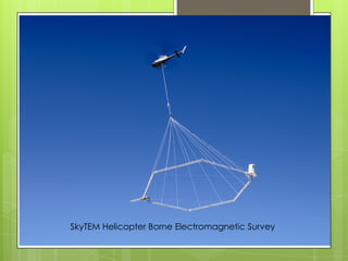
- 9. SkyTEM Helicopter Borne Electromagnetic Survey
- 10. System Design ŌĆó The SkyTEM is a stand-alone system; no personnel other than the pilot are required on board the helicopter to operate the equipment. ŌĆó The transmitter and receiver coils, power supplies, laser altimeters, global positioning system (GPS), electronics, and data logger are carried as a sling load from the cargo hook of the helicopter. ŌĆó The selection of measurement parameters, including repetition frequency and time gates, is handled by an operator-controlled command script. ŌĆó The array is located using two GPS instruments. ŌĆó Elevation is measured using two laser altimeters mounted on the transmitter frame, measuring the height 20 times per second.
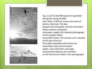
- 11. Fig. 2. (a) The SkyTEM system in operation during the spring of 2003 over Sabro, a 40 km2 survey area west of Aarhus, Denmark. The box between the helicopter and the transmitter lattice contains computers and power supply. (b) A detailed photograph of the wooden lattice transmitter frame. The receiver coil is located at the top of the tail. The cables attached to the frame are transmitter and communication cables. Laser altimeters and angle measurement devices are mounted on the frame (not visible in the photograph).
- 12. ŌĆó Inclinometers are mounted in both the x and y directions. ŌĆó The measured data are averaged, reduced to data subsets (soundings), and stored together with GPS coordinates, altitude and inclination of the transmitter/receiver coils, and transmitter waveform. ŌĆó Transmitter waveform information (current, turn-on and turn-off ramp times) and other controlling parameters of the measuring process are recorded for each data subset, thereby ensuring high data-quality control. ŌĆó Not having an operator in the helicopter reduces the total weight by 75 to 100 kg. ŌĆó A small display is temporarily mounted inside the helicopter, to allow the pilot to monitor the altitude and the inclination of the transmitter and receiver coils, and the status of the receiver/transmitter system.
- 13. ŌĆó The transmitter loop, horizontal and 12.5 m square, is mounted on the wooden lattice frame. ŌĆó The total weight of the system including the electronics, power supply, GPS, and other related instruments is about 280 kg. ŌĆó The SkyTEM system operates continuously while the helicopter is airborne with sufficient transmitter power for about 2 hours of operation, more than the fuel endurance of the helicopter.
- 14. Array Configuration & Transmitter System TRANSMITTER COIL ŌĆó The transmitter is a four-turn 12.5 12.5 m2 square loop divided into segments to allow transmitting with a low moment using one turn, and a high moment using all four turns. ŌĆó The transmitter current for the low moment is about 35 A resulting in a turn-off time of about 4 ┬Ąs. The high moment has a turn-off time of about 80 ┬Ąs transmitting with approximately 50 A. ŌĆó The transmitter loop is attached to a wooden lattice frame constructed without any metal.
- 15. RECEIVER COIL ŌĆó The receiver coil (dimensions 0.5 0.5 m) is located 1.5 m above the corner of the transmitter loop. This configuration is practically a central-loop with a vertical offset. ŌĆó The lattice framework ensures an extremely stiff structure resulting in rigid control of the relative position of receiver coil with respect to the transmitter. CENTRAL LOOP CONFIGURATION ADVANTAGE As analysed with one-dimensional (1D) modelling, the central-loop configuration is preferable to the offset-loop configuration because it is insensitive to near- surface resistivity variations and small changes in the transmitter-receiver separation.
- 16. Fig. 3. The solid grey line is the theoretical transmitter waveform showing the linear and exponential regimes of turn-on and turn-off current. The piece-wise linear waveform used in modelling is shown as a black dotted line. For comparison, the location of the first gate is shown to the right.
- 17. Receiver System ŌĆó The receiver coil is a shielded, overdamped, multi-turn loop, with a first order cut-off frequency of 450 kHz. ŌĆó The effective receiver area is 31.4 m2. ŌĆó The SkyTEM receiver system uses two embedded computers that are electrically separated. One computer controls and stores the measurements from the receiver coil while the other controls the transmitter and logs the transmitted waveform, GPS coordinates, laser altitude, and angle data. ŌĆó The receiver system uses synchronous detection with online data stacking. ŌĆó The receiver integrates the incoming voltages by applying a digital controlled integrator.
- 18. ŌĆó The integrator output is measured in time steps of 6 ┬Ąs (16 bit words) but the width of the integrator itself is controlled in time steps of 0.2 ┬Ąs. ŌĆó The incoming signal from the receiver coil is used in the time range from about 20 ┬Ąs to about 4 ms as measured from the beginning of the ramp. ŌĆó The time gates are linearly spaced until 100 ┬Ąs, after which they are logarithmically spaced with 10 gates per decade.
- 19. Fig. 4. A typical transient decay curve with time gates starting at the beginning of the ramp. The black curves depict the low and high moment transient decays. The curves in grey denote those parts of the data that are not used in subsequent modelling.
- 20. Flight Speed and Altitude FLIGHT SPEED ŌĆó The flight speed and altitude of operation are crucial parameters for resolution of the subsurface resistivity distribution. ŌĆó The operational flight speed of the SkyTEM system is 15 to 20 km per hour (4.1 to 5.5 m/s or 8ŌĆō11 knots). ŌĆó This results in a high-moment stack size of approximately 1000 transients. This is sufficient to obtain data out to 2 to 4 ms. ŌĆó Increasing the transmitter moment leads to a larger turn-off time, but allows greater flight speed and production rate, or an increased depth of penetration.
- 21. FLIGHT ALTITUDE ŌĆó The spatial resolution of near-surface resistivity structures decreases with increasing flight altitude because the fields are upward-continued from the ground surface. ŌĆó Reasonable compromise between resolution and safety concerns for the helicopter and SkyTEM system is to operate so that the transmitter loop is at an altitude of 15 to 20 m, and the helicopter is at about 50 m.
- 22. MODELLING OF SKYTEM DATA ŌĆó About 1000 SkyTEM transients are averaged into a sounding yielding data starting from 20 ┬Ąs and ending at between 2 to 4 ms. ŌĆó The system transfer function is not deconvolved from the field data because, deconvolution is an inherently unstable process. ŌĆó The transmitter waveform is applied using a piecewise-linear approximation to the ramp. ŌĆó Filters before the front gate are modelled in the frequency domain while filters after the front gate are modelled by a convolution in the time domain. ŌĆó A sounding consists of low- and high-moment segments. ŌĆó The two segments are spatially separated (the system has moved between the soundings) hence the datasets are inverted with different altitudes.
- 23. Aquifer Mapping ŌĆó The Sabro survey covers about 40 km2 with an average line spacing of 250 m for approximately 200 line kilometres of data. ŌĆó Aquifers in this part of the country are often associated with buried valleys incised into the low-resistivity tertiary clays. ŌĆó The valleys, filled with sand and gravel deposits, are the primary aquifers. The purpose of the Sabro survey is to find and delineate these buried valley structures. ŌĆó The tertiary clay is well defined with resistivity values less than 20 Ōä”.m (blue colours). ŌĆó The profile shows two distinct buried valleys around profile locations 500 m and 8000 m. ŌĆó The valleys are filled with sand and gravel, indicated by resistivity values greater than 50 Ōä”.m (yellows and greens).
- 24. Fig. 5. Site map of the Sabro survey. The black dots show the individual soundings at the flight lines. The red line is the location of the profile shown in Figure 10. The location of a selected sounding is marked on the profile. The sounding and the inverted model are shown in Figure 11. The area is 6 9 km.
- 25. Fig. 6. Resistivity depth section. The location of a sounding is marked on the profile and shown in Figure 11.
- 26. Fig. 7. A typical SkyTEM sounding, with the inverted 1D MCI model.
- 27. Conclusion ŌĆó SkyTEM system can efficiently acquire reliable, accurate TEM data that is comparable to that collected with a standard ground-based system for hydrogeophysical work. ŌĆó The wooden lattice framework makes the system lightweight and portable so that it can be shipped and used with any helicopter anywhere in the world. ŌĆó System parameter definitions are performed from the ground requiring only the pilot in the helicopter. ŌĆó The system is designed to be flown at an altitude of 10 to 20 m, with the helicopter at about 50 m, and a flight speed of 15 to 20 km per hour. ŌĆó This results in a high-moment stack size of approximately 1000 transients, which is sufficient to obtain data out to 2 to 4 ms, for a sounding every 40 m
- 28. References 1. SkyTEM ŌĆō a new high-resolution helicopter transient electromagnetic system Kurt I. S├Ėrensen1 Esben Auken2 2. An overview of the SkyTEM airborne EM system with Australian examples James Reid1,4, Andrew Fitzpatrick2 and Kate Godber3 3. A comparison of helicopter-borne electromagnetics in frequency- and time-domain at the Cuxhaven valley in Northern Germany Annika Steuera,ŌüÄ, BernhardSiemona, Esben Aukenb
- 29. Thank You!