Design of plate girder by LSM flexural cross section.ppt
Download as PPT, PDF0 likes7 views

Plate girders are typically used as long-span floor girders in buildings, as bridge girders, and as crane girders in industrial structures. Commonly term girder refers to a flexural cross section made up of a number of elements. They are generally considerably deeper than the deepest rolled sections and usually have webs thinner than rolled sections. Plate girders are at their most impressive in modern bridge construction where main spans of well over 200m are feasible, with corresponding cross- section depths, haunched over the supports, in the range of 5-10m.


More Related Content
Similar to Design of plate girder by LSM flexural cross section.ppt (20)
Recently uploaded (20)


Design of plate girder by LSM flexural cross section.ppt
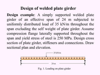
- 1. Design of welded plate girder Design example: A simply supported welded plate girder of an effective span of 24 m subjected to uniformly distributed load of 35 kN/m throughout the span excluding the self weight of plate girder. Assume compression flange laterally supported throughout the span and yield stress of steel is 250 MPa. Design cross section of plate girder, stiffeners and connections. Draw sectional plan and elevation. Fig. 1. Loading on plate girder 35 kN/m 24 m
- 2. Maximum bending moment and shear force Self weight of plate girder Factored load = 35 x 1.5 = 52.5 kN/m Self weight of plate girder, w1 = W/200 = 6.3 kN/m. Total uniformly distributed load on plate girder, wT = 58.8 kN/m. Maximum bending moment M = 58.8 x 242 /8 = 4233.6 kNm. Maximum shear force F = 58.8 x 24/2 = 705.6 kN.
- 3. Design of web plate If stiffener spacing c is in between d and 3d, where d is depth of web, then serviceability requirement is, k = d/tw Ōēż 200, considering, k = 190 Economical depth, d = = 1473.29 mm = 1500 mm tw = 1500/190 = 7.89 mm Provide 1500 mm deep and 8 mm thick web plate. Provide intermediate stiffeners at a spacing of 2000 mm centre to centre.(3d Ōēź c Ōēż d) 3 1 y f Mk ’ā║ ’ā╗ ’ā╣ ’ā¬ ’ā½ ’ā®
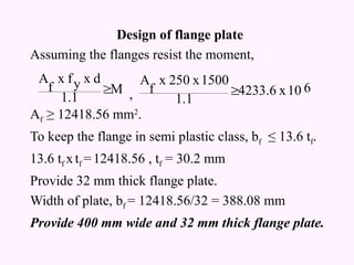
- 4. Design of flange plate Assuming the flanges resist the moment, , Af Ōēź 12418.56 mm2 . To keep the flange in semi plastic class, bf Ōēż 13.6 tf. 13.6 tf xtf =12418.56 , tf = 30.2 mm Provide 32 mm thick flange plate. Width of plate, bf = 12418.56/32 = 388.08 mm Provide 400 mm wide and 32 mm thick flange plate. M 1.1 d x y f x f A ’é│ 6 10 x 4233.6 1.1 1500 x 250 x f A ’é│
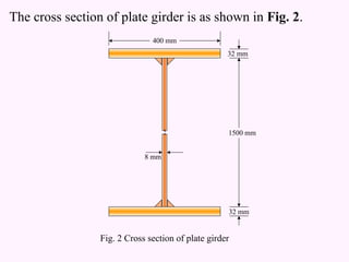
- 5. The cross section of plate girder is as shown in Fig. 2. 400 mm 32 mm 32 mm 1500 mm 8 mm Fig. 2 Cross section of plate girder
- 6. Check for shear buckling of web. Using simple post critical method as per clause 8.4.2.2 of IS 800: 2007. If c/d Ōēź 1.0 then 7.6 1500 2000 4 5.35 d c 4 5.35 K 2 2 v ’ĆĮ ’āĘ ’āĖ ’āČ ’ā¦ ’ā© ’ā” ’Ć½ ’ĆĮ ’āĘ ’āĖ ’āČ ’ā¦ ’ā© ’ā” ’Ć½ ’ĆĮ ’Ć© ’Ć® ’Ć© ’Ć® 08 39 8 1500 3 0 1 12 10 2 6 7 1 12 2 2 5 2 2 2 2 . . x x x ŽĆ . t d ╬╝ E ŽĆ K Žä w v cr ’ĆĮ ’āĘ ’āĖ ’āČ ’ā¦ ’ā© ’ā” ’ĆŁ ’ĆĮ ’āĘ ’āĖ ’āČ ’ā¦ ’ā© ’ā” ’ĆŁ ’ĆĮ 1.92 39.08 x 3 250 x Žä 3 f cr yw w ’ĆĮ ’ĆĮ ’ĆĮ ’ü¼
- 7. If ╬╗w > 1.2 Vn = Vcr = Av x Žäb = 1500 x 8 x 39.15 = 469.8 kN < 705.6 kN. Since Vn is less than the maximum shear force, hence intermediate stiffener to be used to improve buckling strength of slender web and end panel should be check for shear capacity as per clause 8.5.3 of IS 800: 2007 Mpa 39.15 1.92 x 3 250 ╬╗ 3 f Žä 2 2 w yw b ’ĆĮ ’ĆĮ ’ĆĮ
- 8. Shear capacity of end panel 3 y f x t x d p V ’ĆĮ N 3 10 x 1732.05 3 250 x 8 x 1500 ’ĆĮ ’ĆĮ ’āĘ ’āĘ ’āĖ ’āČ ’ā¦ ’ā¦ ’ā© ’ā” ’ĆŁ ’ĆĮ p cr p q V V 1 V 1.25 H kN 924.13 2 H R q tf ’ĆĮ ’ĆĮ kN 1848.26 1732.05 469.8 1 1732.05 x 1.25 ’ĆĮ ’āĘ ’āĖ ’āČ ’ā¦ ’ā© ’ā” ’ĆŁ ’ĆĮ
- 9. Mtf = The end panel to be checked as a beam spanning between the flanges to resist Rtf and Mtf. Area resisting shear = tw x d = 8 x 1500 = 12000 mm2 . kNm 277.239 10 1500 x 1848.26 10 d Hq ’ĆĮ ’ĆĮ kN 705.6 N x10 1574.59 1.1 x 3 250 x 12000 ╬│ 3 f A V 3 mo yw v d ’ā▒ ’ĆĮ ’ĆĮ ’ĆĮ
- 10. End panel can carry the shear due to anchoring force. ymax = c/2 = 1000 mm. Hence end panel can carry the bending moment due to anchor force. . mm 10 x 5333.3 12 2000 x 8 12 c t I 4 6 3 3 w ’ĆĮ ’ĆĮ ’ĆĮ 1.1 x 1000 250 x 10 x 5333.33 x ╬│ y f x I M 3 mo max y q ’ĆĮ ’ĆĮ tf M kNm 1212.12 ’ā▒ ’ĆĮ
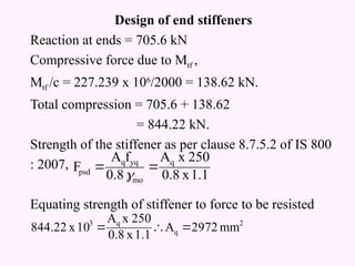
- 11. Design of end stiffeners Reaction at ends = 705.6 kN Compressive force due to Mtf , Mtf /c = 227.239 x 10⁶ /2000 = 138.62 kN. Total compression = 705.6 + 138.62 = 844.22 kN. Strength of the stiffener as per clause 8.7.5.2 of IS 800 : 2007, Equating strength of stiffener to force to be resisted 2 q q 3 mm 2972 A 1.1 x 0.8 250 x A 10 x 844.22 ’ĆĮ ’ü£ ’ĆĮ 1.1 x 0.8 250 x A 0.8 f A F q mo yq q psd ’ĆĮ ’ĆĮ ’ü¦
- 12. Provide 180 mm wide and 10 mm thick flats on either side of web. Then provided is, 2 x 180 x 10 = 3600 mm2 . Check for outstand: It should not be more than 20 Since it is more than 14 , 14 x 10 = 140 mm. Core area of each stiffener = 140 x 10 = 1400 mm2 . Buckling check for stiffener Effective area = 2 x 140 x 10 = 2800 mm2 . r = (36.34 x 10⁶ /2800)0.5 = 113.9 mm. q t q A q t ’Ć© ’Ć® 4 6 3 s mm 10 x 36.34 12 8 - 360 10 I ’ĆĮ ’ĆĮ
- 13. KLc = 0.7 x 1500 = 1050 mm. slenderness ratio = 1050/113.9 = 9.22 from table 9c of IS 800: 2007 fcd = 227 Mpa. Assuming 20 x web thickness on only one side, effective area = 2 x 140 x 10 + 20 x 8 x 8 = 6000 mm2 . Buckling resistance of stiffener = 4080 x 227 = 926.16 kN > 844.22 kN. Check for load carrying capacity of stiffener As per clause 8.7.4 of IS 800: 2007, taking stiff bearing, b1 = 0 n2 = 2.5 x tf = 2.5 x 32 = 80 mm.
- 14. Local capacity of web The stiffener is to be designed for a force 844.22 ŌĆō 145.45 = 698.766 kN. fcd = 227 Mpa. Area of stiffener alone, 2 x 180 x 10 = 3600 mm2 . Bearing capacity of stiffener alone, Hence the stiffeners are safe. Provide 180 mm wide and 10 mm thick flat as a stiffener. ’Ć© ’Ć® ’Ć© ’Ć® kN 145.45 1.1 250 x 8 x 80 0 ╬│ f t n b F mo yw w 2 1 w ’ĆĮ ’Ć½ ’ĆĮ ’Ć½ ’ĆĮ kN 698.766 kN 742.9 1.1 3600 x 227 ’ā▒ ’ĆĮ
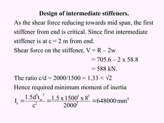
- 15. Design of intermediate stiffeners. As the shear force reducing towards mid span, the first stiffener from end is critical. Since first intermediate stiffener is at c = 2 m from end. Shear force on the stiffener, V = R ŌĆō 2w = 705.6 ŌĆō 2 x 58.8 = 588 kN. The ratio c/d = 2000/1500 = 1.33 < ŌłÜ2 Hence required minimum moment of inertia 4 2 3 3 2 3 w 3 s mm 648000 2000 8 x 1500 x 1.5 c t 1.5d I ’ĆĮ ’ĆĮ ’ĆĮ
- 16. Provide intermediate stiffener of size 120 mm wide and 10 mm thick which satisfy the condition of outstand. 12.71 x 106 mm4 . > Is required. Hence o. k. Checking for buckling Shear buckling resistance of web alone, Vcr = 469.8 kN Shear strength of stiffener alone required = (V-Vcr)/╬│mo. (588 ŌĆō 469.8)/1.1 = 107.45 kN. Buckling resistance of intermediate stiffener as per clause 8.7.15 of IS 800: 2007. ’Ć© ’Ć® 12 8 x 10 12 120 8 120 10 I 3 3 s ’ĆŁ ’Ć½ ’Ć½ ’ĆĮ
- 17. Considering 20 tw = 160 mm width of web on both side along with stiffener. Area = 2 x 120 x 10 + 2 x 160 x 8 = 4960 mm2 . r = ( 12.73 x 10⁶ /4960) 0.5 = 50.66 mm KL/r = (0.7 x 1500)/50.66 = 20.72 From table 9c of IS 800: 2007, fcd = 223.78 Mpa Buckling resistance = 223.78 x 4960/1000 = 1109.97 kN > 107.45 kN. Hence safe. 4 6 3 s x mm 10 x 12.73 12 8 x 160 x 2 I I ’ĆĮ ’Ć½ ’ĆĮ
- 18. Design of weld between flange and web plates Maximum shear force = 705.6 kN Shear stress at the joint of flange and web Shear force per mm length = 401.2 N/mm If s is the size of shop weld, then throat thickness 0.7 s. Providing weld on both side of web, strength of weld per mm length is, Equating shear force to strength of weld per mm length 2 6 3 N/mm 1.003 00 4 x 10 x 17273.14 788 x 32 x 400 x 10 x 705.6 Ib y FA Žä ’ĆĮ ’ĆĮ ’ĆĮ s 265.1 1.25 1 x 3 410 x s 0.7 x 2 ’ĆĮ
- 19. s = 1.513 mm. Provide 5 mm intermittent weld on both side of web plate with weld length of 40 mm and at an spacing of 120 mm centre to centre. Design of weld between bearing stiffeners and web plates Shear carried by web: fcd = 24.3 Mpa, mm 453.75 8 1500 2.42 t d 2.42 ╬╗ ’ĆĮ ’ĆĮ ’ĆĮ mm 782 2 D n1 ’ĆĮ ’ĆĮ
- 20. Area of web resisting shear, btw = 742 x 8 = 5936 mm2 . Load transmitted by web = 5936 x 24.3 = 144.24 kN. Shear to be transferred through weld = reaction - shear transfer by web = 705.6 - 144.24 = 561.36 kN Length of weld = 1500 - 2 x 8 = 1484 mm Shear stress per mm length = 561.36/1484 = 0.378 kN/mm
- 21. Additional shear = Total shear per mm length = 0.469 kN/mm = 469 N/mm If s is the size of fillet weld to be provided on both side then strength of weld per mm length. Equating shear to strength of weld per mm length 265.12 s = 469, s = 1.769 mm kN/mm 0.091 140 x 5 8 5b tw 2 s 2 ’ĆĮ ’ĆĮ N/mm s 265.12 1.25 1 x 3 410 x s 0.7 x 2 ’ĆĮ
- 22. Provide 5 mm intermittent weld on both side of web plate with weld length of 40 mm and at an spacing of f 120 mm centre to centre. Design similar welded connection between intermediate stiffener and web plate.
- 23. Bearing Stiffener Intermediate Stiffener Flange plate Web Plate 20 t p p p Sectional plan
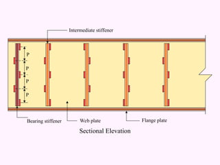
- 24. Intermediate stiffener Bearing stiffener Web plate Flange plate P P P P Sectional Elevation