際際滷

際際滷Share a Scribd company logo
Submitted by
Md. Redwan Islam(1006066)
Md. Rayhan Khan (1006067)
Nurani saoda (1006176)
Rakib Hasan (1006180)
Umme Fatema (1006194)
Farhan Shams (0806152)
Digital Filter Bank
A digital Filter Bank is a set of digital bandpass filters
either a common input or summed output.
The figure shows an M-band analysis filter bank with
Hk(z) as the analysis filter and Hk(z) decomposes the
input signal into M-subband signals.
Figure 01: Digital Filter Bank
Analysis filter bank Synthesis filter bank
Uniform Filter Bank
The uniform filter bank is composed of M filters which are
uniformly shifted versions of the basic prototype filter.
According to the definetion a uniform filter bank,
Hk(ejw) = Ho(ej(w-2k/M)) ; 0 k  (M-1)
Where Ho(ejw) is the basic prototype filter.
Figure 02: Unifomly Shifted Filter Bank
Uniform Filter Bank using Multirate
Concept
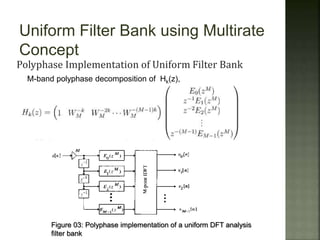
Polyphase Implementation of Uniform Filter Bank
M-band polyphase decomposition of Hk(z),
Figure 03: Polyphase implementation of a uniform DFT analysis
filter bank
For k= 0,1,2. M-1,
Figure 04: Uniform DFT analysis filter bank
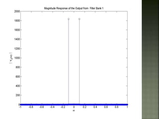
Outputs of frequency
response of some of the
filters of M band Analysis
Filter Bank
with M=20
Designing a uniform filter bank using multirate concept
FFT of an input
comprising of
sinusoids with
different magnitudes
Designing a uniform filter bank using multirate concept
Few major applications of uniform digital
filter bank are:
 Digital Audio Systems
 Sub-band Coding of Speech and Image
Signals
 Analog Voice Privacy Systems
 The prototype filter was chosen to be FIR filter for
the ease of calculation and polyphase
decomposition.
 Commutation operation was implemented by
reshaping the prototype impulse response which
also formed the banks.
 All the outputs, e.g. magnitude response of the
impulse response of the filters, magnitude
response of the input and output of each bank
and reconstruction observed in frequency domain,
since, only frequency domain gives the perfect
visualization of the signal.

More Related Content

Designing a uniform filter bank using multirate concept

  • 1. Submitted by Md. Redwan Islam(1006066) Md. Rayhan Khan (1006067) Nurani saoda (1006176) Rakib Hasan (1006180) Umme Fatema (1006194) Farhan Shams (0806152)
  • 2. Digital Filter Bank A digital Filter Bank is a set of digital bandpass filters either a common input or summed output. The figure shows an M-band analysis filter bank with Hk(z) as the analysis filter and Hk(z) decomposes the input signal into M-subband signals. Figure 01: Digital Filter Bank Analysis filter bank Synthesis filter bank
  • 3. Uniform Filter Bank The uniform filter bank is composed of M filters which are uniformly shifted versions of the basic prototype filter. According to the definetion a uniform filter bank, Hk(ejw) = Ho(ej(w-2k/M)) ; 0 k (M-1) Where Ho(ejw) is the basic prototype filter. Figure 02: Unifomly Shifted Filter Bank
  • 4. Uniform Filter Bank using Multirate Concept Polyphase Implementation of Uniform Filter Bank M-band polyphase decomposition of Hk(z), Figure 03: Polyphase implementation of a uniform DFT analysis filter bank
  • 5. For k= 0,1,2. M-1, Figure 04: Uniform DFT analysis filter bank
  • 6. Outputs of frequency response of some of the filters of M band Analysis Filter Bank with M=20
  • 12. FFT of an input comprising of sinusoids with different magnitudes
  • 20. Few major applications of uniform digital filter bank are: Digital Audio Systems Sub-band Coding of Speech and Image Signals Analog Voice Privacy Systems
  • 21. The prototype filter was chosen to be FIR filter for the ease of calculation and polyphase decomposition. Commutation operation was implemented by reshaping the prototype impulse response which also formed the banks. All the outputs, e.g. magnitude response of the impulse response of the filters, magnitude response of the input and output of each bank and reconstruction observed in frequency domain, since, only frequency domain gives the perfect visualization of the signal.