Digital communications 1
•Download as PPTX, PDF•
7 likes•8,513 views

The document discusses various digital communication techniques including linear vs nonlinear PCM encoding, idle channel noise reduction methods, coding methods like level-at-a-time, digit-at-a-time and word-at-a-time. It also discusses analog companding using A-law and μ-law, digital companding, vocoders, delta modulation, DPCM, intersymbol interference causes and eye patterns.

Digital communications 1
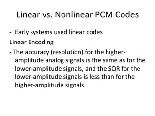
- 2. Linear vs. Nonlinear PCM Codes - Early systems used linear codes Linear Encoding - The accuracy (resolution) for the higher- amplitude analog signals is the same as for the lower-amplitude signals, and the SQR for the lower-amplitude signals is less than for the higher-amplitude signals.
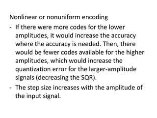
- 3. Nonlinear or nonuniform encoding - If there were more codes for the lower amplitudes, it would increase the accuracy where the accuracy is needed. Then, there would be fewer codes available for the higher amplitudes, which would increase the quantization error for the larger-amplitude signals (decreasing the SQR). - The step size increases with the amplitude of the input signal.
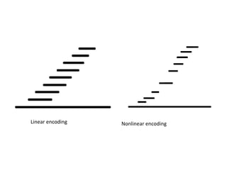
- 4. Linear encoding Nonlinear encoding
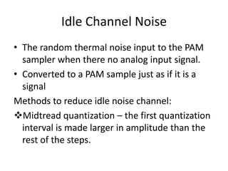
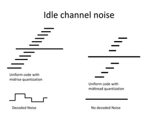
- 5. Idle Channel Noise • The random thermal noise input to the PAM sampler when there no analog input signal. • Converted to a PAM sample just as if it is a signal Methods to reduce idle noise channel: Midtread quantization – the first quantization interval is made larger in amplitude than the rest of the steps.
- 6. Midrise Quantization – the lowest-magnitude positive and negative codes have the same voltage range as all the other codes (+ or – one-half the resolution).
- 7. Idle channel noise Uniform code with midrise quantization Uniform code with midtread quantization Decoded Noise No decoded Noise
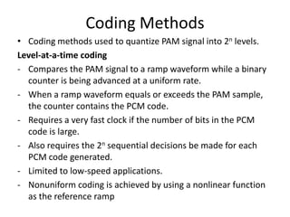
- 8. Coding Methods • Coding methods used to quantize PAM signal into 2n levels. Level-at-a-time coding - Compares the PAM signal to a ramp waveform while a binary counter is being advanced at a uniform rate. - When a ramp waveform equals or exceeds the PAM sample, the counter contains the PCM code. - Requires a very fast clock if the number of bits in the PCM code is large. - Also requires the 2n sequential decisions be made for each PCM code generated. - Limited to low-speed applications. - Nonuniform coding is achieved by using a nonlinear function as the reference ramp
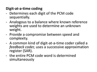
- 9. Digit-at-a-time coding - Determines each digit of the PCM code sequentially. - Analogous to a balance where known reference weights are used to determine an unknown weight. - Provide a compromise between speed and complexity. - A common kind of digit-at-a-time coder called a feedback coder, uses a successive approximation register (SAR). - the entire PCM code word is determined simultaneously
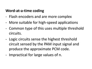
- 10. Word-at-a-time coding - Flash encoders and are more complex - More suitable for high-speed applications - Common type of this uses multiple threshold circuits. - Logic circuits sense the highest threshold circuit sensed by the PAM input signal and produce the approximate PCM code. - Impractical for large values of n.
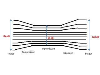
- 11. - The process of compressing, then expanding. - The higher-amplitude analog signals are compressed (less than the lower-amplitude signals) prior to transmission, then expanded (more than the smaller-amplitude signals) at the receiver.
- 12. 120 dB 120 dB 60 dB Transmission Compression Expansion input output
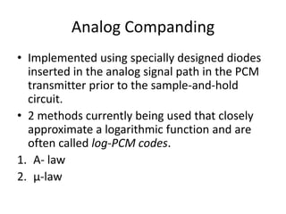
- 13. Analog Companding • Implemented using specially designed diodes inserted in the analog signal path in the PCM transmitter prior to the sample-and-hold circuit. • 2 methods currently being used that closely approximate a logarithmic function and are often called log-PCM codes. 1. A- law 2. μ-law
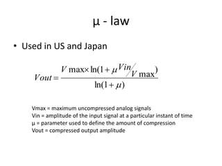
- 14. μ - law • Used in US and Japan V max ln(1   Vin ) Vout  V max ln(1   ) Vmax = maximum uncompressed analog signals Vin = amplitude of the input signal at a particular instant of time μ = parameter used to define the amount of compression Vout = compressed output amplitude
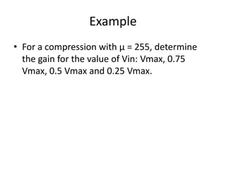
- 15. Example • For a compression with μ = 255, determine the gain for the value of Vin: Vmax, 0.75 Vmax, 0.5 Vmax and 0.25 Vmax.
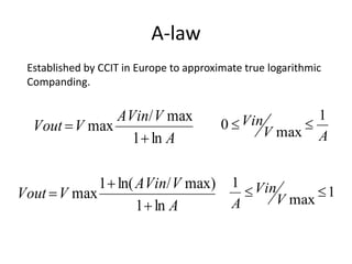
- 16. A-law Established by CCIT in Europe to approximate true logarithmic Companding. AVin/ V max 1 Vout ÔÄΩ V max 0ÔÇ£ Vin ÔÇ£ 1 ÔÄ´ ln A V max A 1 ÔÄ´ ln( AVin/ V max) 1 Vin Vout ÔÄΩ V max ÔÇ£ ÔÇ£1 1 ÔÄ´ ln A A V max
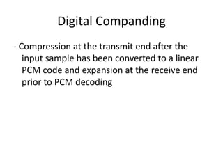
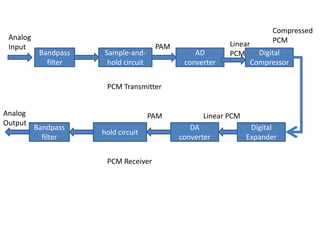
- 17. Digital Companding - Compression at the transmit end after the input sample has been converted to a linear PCM code and expansion at the receive end prior to PCM decoding
- 18. Compressed Analog PCM Input PAM Linear Bandpass Sample-and- AD PCM Digital filter hold circuit converter Compressor PCM Transmitter Analog PAM Linear PCM Output Bandpass DA Digital hold circuit filter converter Expander PCM Receiver
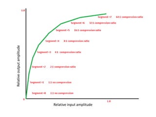
- 19. Relative output amplitude Relative input amplitude
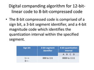
- 20. Digital companding algorithm for 12-bit- linear code to 8-bit-compressed code • The 8-bit compressed code is comprised of a sign bit, a 3-bit segment identifier, and a 4-bit magnitude code which identifies the quantization interval within the specified segment. Sign bit 3-bit segment 4-bit quantization identifier interval A B C D 1=+ 000 to 111 0000 to 1111 0=-
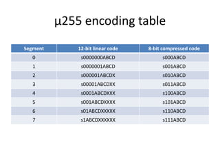
- 21. μ255 encoding table Segment 12-bit linear code 8-bit compressed code 0 s0000000ABCD s000ABCD 1 s0000001ABCD s001ABCD 2 s000001ABCDX s010ABCD 3 s00001ABCDXX s011ABCD 4 s0001ABCDXXX s100ABCD 5 s001ABCDXXXX s101ABCD 6 s01ABCDXXXXX s110ABCD 7 s1ABCDXXXXXX s111ABCD
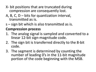
- 22. X- bit positions that are truncated during compression are consequently lost. A, B, C, D – bits for quantization interval, transmitted as is. s – sign bit which is also transmitted as is. Compression process 1. The analog signal is sampled and converted to a linear 12-bit sign-magnitude code. 2. The sign bit is transferred directly to the 8-bit code. 3. The segment is determined by counting the number of leading 0’s in the 11-bit magnitude portion of the code beginning with the MSB.
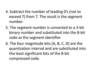
- 23. 4. Subtract the number of leading 0’s (not to exceed 7) from 7. The result is the segment number. 5. The segment number is converted to a 3-bit binary number and substituted into the 8-bit code as the segment identifier. 6. The four magnitude bits (A, B, C, D) are the quantization interval and are substituted into the least significant bits of the 8-bit compressed code.
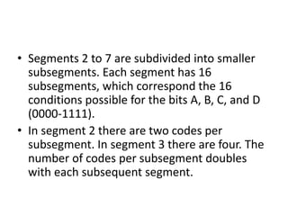
- 24. • Segments 2 to 7 are subdivided into smaller subsegments. Each segment has 16 subsegments, which correspond the 16 conditions possible for the bits A, B, C, and D (0000-1111). • In segment 2 there are two codes per subsegment. In segment 3 there are four. The number of codes per subsegment doubles with each subsequent segment.
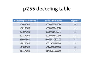
- 25. μ255 decoding table 8-bit compressed code 12-bit linear code Segment s000ABCD s0000000ABCD 0 s001ABCD s0000001ABCD 1 s010ABCD s000001ABCD1 2 s011ABCD s00001ABCD10 3 s100ABCD s0001ABCDX100 4 s101ABCD s001ABCD1000 5 s110ABCD s01ABCD10000 6 s111ABCD s1ABCD100000 7
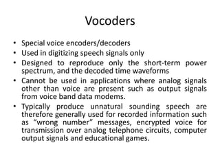
- 26. Vocoders • Special voice encoders/decoders • Used in digitizing speech signals only • Designed to reproduce only the short-term power spectrum, and the decoded time waveforms • Cannot be used in applications where analog signals other than voice are present such as output signals from voice band data modems. • Typically produce unnatural sounding speech are therefore generally used for recorded information such as “wrong number” messages, encrypted voice for transmission over analog telephone circuits, computer output signals and educational games.
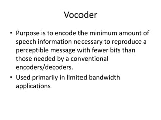
- 27. Vocoder • Purpose is to encode the minimum amount of speech information necessary to reproduce a perceptible message with fewer bits than those needed by a conventional encoders/decoders. • Used primarily in limited bandwidth applications
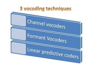
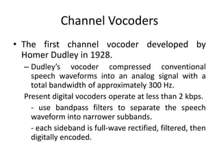
- 29. Channel Vocoders • The first channel vocoder developed by Homer Dudley in 1928. – Dudley’s vocoder compressed conventional speech waveforms into an analog signal with a total bandwidth of approximately 300 Hz. Present digital vocoders operate at less than 2 kbps. - use bandpass filters to separate the speech waveform into narrower subbands. - each sideband is full-wave rectified, filtered, then digitally encoded.
- 30. Channel Vocoder • The quality of the signal is at the output is quite poor. • More advanced channel vocoders operate at 2400 bps and produce a highly intelligible, although slightly synthetic sounding speech.
- 31. • The spectral power of most speech energy concentrates at three or four peak frequencies called formants. • Determines the location of these peaks and encodes and transmits only the information with the most significant short- term components. • Can operate at lower bit rates and thus require narrow bandwidths. • Sometimes have trouble tracking changes in the formants. • Once the formants have been identified, a formant vocoder can transfer intelligible speech at less than 1000 bps.
- 32. • Extracts the most significant portions of speech information directly from the time waveform rather than from the frequency spectrum as with the channel and formant vocoders. • Produces a time-varying model of the vocal tract excitation and transfer function directly from the speech waveform. • At the receive end, a synthesizer reproduces the speech by passing the specified excitation through a mathematical model of the vocal tract. • Provide more-natural-sounding speech than does either the channel or formant vocoder. • Encode and transmit speech at between 1.2 and 2.4 kbps.
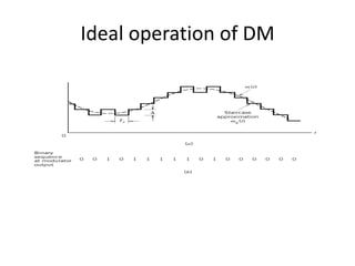
- 33. • most popular alternative to PCM • Uses a single-bit PCM code to achieve digital transmission of analog signals. • Rather than transmit a coded representation of the sample, only a single bit is transmitted which simply indicates whether that sample is larger or smaller than the previous sample. • If the current sample is smaller than the previous sample, a logic 0 is transmitted, if it is larger than the previous sample, a logic 1 is transmitted.
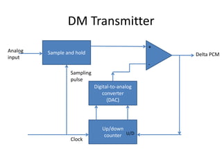
- 34. DM Transmitter + Analog Sample and hold Delta PCM input - Sampling pulse Digital-to-analog converter (DAC) Up/down counter U/D Clock
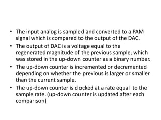
- 35. • The input analog is sampled and converted to a PAM signal which is compared to the output of the DAC. • The output of DAC is a voltage equal to the regenerated magnitude of the previous sample, which was stored in the up-down counter as a binary number. • The up-down counter is incremented or decremented depending on whether the previous is larger or smaller than the current sample. • The up-down counter is clocked at a rate equal to the sample rate. (up-down counter is updated after each comparison)
- 36. Ideal operation of DM
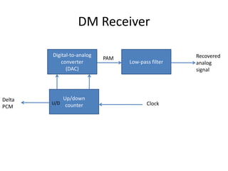
- 37. DM Receiver Digital-to-analog Recovered PAM converter Low-pass filter analog (DAC) signal Delta Up/down U/D counter Clock PCM
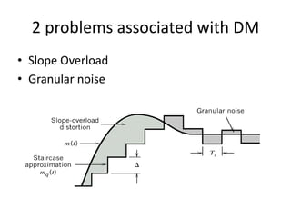
- 38. 2 problems associated with DM • Slope Overload • Granular noise
- 39. • Slope overload – when the analog input signal changes at a faster rate than the DAC can keep up with. – The slope of the analog signal is greater than the delta modulator can maintain. – Increasing the clock frequency reduces the probability of slope overload occurrences. – Another way is to increase the magnitude of the minimum step size.
- 40. • Granular noise - when the original analog input signal has a relatively constant amplitude, the reconstructed signal has variations that were not present in the original signal. – Analogous to quantization noise in conventional PCM. – Can be reduced by decreasing the step size.
- 41. • To reduce the granular noise, a small resolution is needed, and to reduce the possibility of slope overload occurring, a large resolution is required. • Granular noise is more prevalent in analog signals that have gradual slopes and whose amplitudes vary only a small amount; slope overload is more prevalent in analog signals that have steep slopes or whose amplitudes vary rapidly.
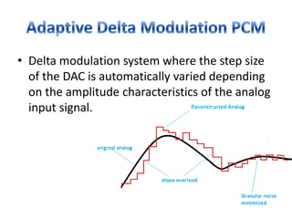
- 42. • Delta modulation system where the step size of the DAC is automatically varied depending on the amplitude characteristics of the analog input signal.
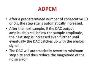
- 43. • After a predetermined number of consecutive 1’s or 0’s, the step size is automatically increased. • After the next sample, if the DAC output amplitude is still below the sample amplitude, the next step is increased even further until eventually the DAC catches up with the analog signal. • The DAC will automatically revert to minimum step size and thus reduce the magnitude of the noise error.
- 44. ADPCM Algorithm • When 3 consecutive 1’s or 0’s occur, the step size of the DACs is increased or decreased by a factor of 1.5.
- 45. • Designed specifically to take advantage of the sample-to-sample redundancies in typical speech waveforms. • The difference of the amplitude of two successive samples is transmitted rather than the actual sample. • Fewer bits are required than conventional PCM.
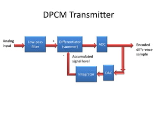
- 46. DPCM Transmitter Analog Low-pass + Differentiator input ADC Encoded filter (summer) difference - sample Accumulated signal level Integrator DAC
- 47. DPCM transmitter • The analog input signal is bandlimited to one- half of the sample rate, then compared to the preceding accumulated signal level in the differentiator.
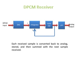
- 48. DPCM + Hold DAC Integrator Analog input Ckt LPF output + Each received sample is converted back to analog, stored, and then summed with the next sample received.
- 49. • All digital carrier systems involve transmission of pulses through a medium with a finite bandwidth. • Practical digital systems utilize filters with bandwidths that are approximately 30% or more in excess of the ideal Nyquist Bandwidth.
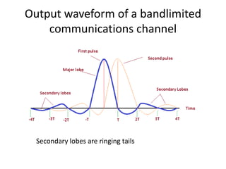
- 50. Output waveform of a bandlimited communications channel Secondary lobes are ringing tails
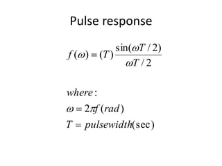
- 51. Pulse response sin(T / 2) f ( )  (T ) T / 2 where :   2f (rad ) T  pulsewidth(sec)
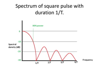
- 52. Spectrum of square pulse with duration 1/T.
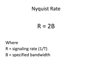
- 53. Nyquist Rate R = 2B Where R = signaling rate (1/T) B = specified bandwidth
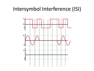
- 55. ISI • Causes crosstalk • Energy in the form of spurious responses from the third and fourth impulses from one pulse appears during the sampling instant (T= 0) of another pulse.
- 56. 4 primary causes of ISI • Timing inaccuracies – if the rate does not conform to the ringing frequency designed into the communications system. • Insufficient Bandwidth • Amplitude distortion • Phase distortion
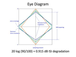
- 57. Eye Patterns • The performance of a digital transmission systems depends, in part, on the ability to regenerate the original pulses. • All waveform combinations are superimposed over adjacent signaling intervals is called eye pattern or eye diagram. • A convenient technique for determining the effects of degradation.
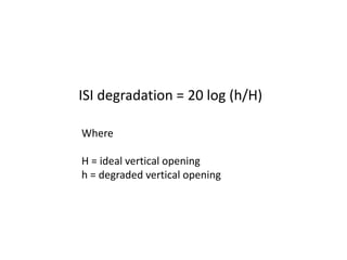
- 58. ISI degradation = 20 log (h/H) Where H = ideal vertical opening h = degraded vertical opening
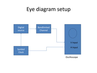
- 59. Eye diagram setup Digital Bandlimited source Channel V Input H Input Symbol Clock Oscilloscope
- 60. Eye Diagram 20 log (90/100) = 0.915 dB ISI degradation