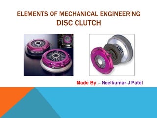
Disc Clutch
- 1. ELEMENTS OF MECHANICAL ENGINEERING DISC CLUTCH Made By â Neelkumar J Patel
- 2. INTRODUCTION ï§ A clutch is a machine member used to connect driving shaft to a driven shaft so that the driven shaft may be started or stopped at will , without stopping the driving shaft. âĒ The use of a clutch is mostly found in automobiles. âĒ A little consideration will show that in order to change gears or to stop the vehicle, It is required that the driven shaft should stop , but the engine should continue to run. âĒ It is , therefore , necessary that driven shaft should be disengaged from the driving shaft. âĒ The engagement and disengagement of the shafts is obtained by means of a clutch which is operated by a lever.
- 3. 3 KEY QUESTIONS HERE: What Is The Purpose Of A Clutch? 1 To allow the driver to operate the engine in its most efficient speed range - nominally 2000 - 3500 RPM, providing an operating speed range of 1500 RPM (Except when moving off from standstill. During this transition mode the engine must briefly operate outside of its designed speed range.) 2 Allows driver to select a suitable gear ratio to increase engine torque (torque multiplication) to match an increased load requirement. (Change down to a lower gear - a higher numerical gear ratio.)
- 4. MAJOR TYPES OF CLUTCHES What Are The Common Types Of Clutches? MECHANICAL ELECTRO-MAGNETIC HYDRO-DYNAMIC
- 5. MAJOR TYPES OF CLUTCHES What Materials Are Clutches Made Of? âĒ A coefficient of friction that remains stable with temperature change âĒ Excellent thermal conductivity âĒ Good wear resistance âĒ Resistance to thermal fatigue âĒ Good high temperature strength âĒ A uniform coefficient of friction over the surface
- 6. This type comprises of dual or multi interfacing between a fibrous friction material facing and a hard metal facing. Can be DRY interfacing or WET interfacing. Dry Plate Clutch Wet Multi Plate Clutch FRICTIONAL ENGAGEMENT DISC/ PLATE CLUTCH
- 7. DRY DISC CLUTCH BASIC ASSEMBLY COMPONENTS ï§ FLYWHEEL FACE ï§ CLUTCH DISC ï§ PRESSURE PLATE ASSEMBLY ( Clutch Cover) ï§ CLUTCH RELEASE MECHANISM ï§ ( Release Bearing, Fork & Attachment, Cable/Hydraulic Release, Pedal)
- 8. DRY DISC CLUTCH// CONTD.. FLYWHEEL ï§ MADE OF CAST IRON/ ALLOY METAL ï§ SURFACE CONDITION ï§ PILOT BEARING ï§ SINGLE / DUAL-MASS FLYWHEELS, WHAT IS THE DIFFERENCE? ï§ WHAT IS THE APPLICATION OF DUAL-MASS FLYWHEEL? WHAT ADVANTAGE IT HAS Single Mass Flywheel Dual Mass Flywheel
- 9. DRY DISC CLUTCH//CONTD.. CLUTCH DISC ï§ ASSEMBLY OF METAL AND COMPOSITE COMPONENTS HELD TOGETHER BY RIVETS AND DOWELS ï§ DESIGN FACTORS, LETS THINK OF THEM AND DISCUSS! ï§ TORQUE TRANSMITTED ï§ SLIP AND WEAR RESISTANCE ï§ KINDNESS TO IRON SURFACES ï§ DISSIPATION OF HEAT ï§ EXPELTION OF SEPATATING DEBRIS ï§ ROTATION DIRECTION ï§ TORSIONAL OSCILLATION DAMPENING ï§ RIGIDITY ï§ SIMPLICITY OF REPAIR
- 10. DRY DISC CLUTCH//CONTD.. PRESSURE PLATE ASSEMBLY ï§ CONFIGURATION ï§ SINGLE PLATE / DUAL OR MULTI PLATE ï§ COIL SPRINGS / DIAPHRAGM SPRING ï§ PUSH RELEASE / PULL RELEASE ï§ MATERIALS USED? ï§ CAST IRON FOR PRESSURE PLATES ï§ SPRING STEEL FOR SPRINGS
- 11. DRY DISC CLUTCH//CONTD.. ï§ Clutch Release Mechanisms: ï§ Can be cable/ rod mechanism. ï§ Can be hydro-mechanical, employing master and slave cylinders using brake fluid. ï§ Can be pneumatically operated, like in commercial vehicles transmissions.
- 13. ï§ Figure shows the typical single disc clutch . There are two flanges . A and B One (A) keyed rigidly to the driving shaft and other (B) fitted to the driven shaft by feather key or splines so that it may be moved along the shaft . Driven flange (B) may be pressed against the driving flange (A) by a suitable mechanism. ï§ The torque is transmitted by friction between the flanges with friction disc . The amount of torque transmitted depends upon axial pressure , radius of the friction surface and co- efficient of friction . Single disc clutches are used in automobiles. ï§ When large torque is to be transmitted , multidisc clutches are used in preference to single disc clutch . Multi disc clutch has more number of contact surfaces having number of driving and driven discs.
- 14. Applications
- 15. âĒ Clutches are used to engage and disengage the transmission of rotary mechanical power from one system element to another. This allows the driven part of the system to be turned on and off by controlling its power supply. âĒ Clutches are used to control the power from one system element to another. This avoids shock loads and damage to the driven parts.
- 16. âĒ Clutches are used to disengage the drive from the driven parts. This allows the drive to be started under âno-load ' conditions, which allows the drive to be operated at its rated conditions when the driven parts are connected to it. The system will be cost efficient because it will be started by a well matched drive. âĒ Clutches are used as over-running devices. An over-running clutch allows the drive to transmit torque to the driven machine in one direction only.
- 17. âĒ Clutches are used as torque limiting devices. A torque limiting clutch responds to the torque difference across the clutch. At a predefined torque difference, it will completely disengage the two components connected, or will allow a predefined amount of torque to be transmitted, dissipating the excess energy.


