ELECTRIC TRACTION IN TRAINS ENGINEERING TOPIC UNDER ELECTRICAL AND ELECTRONICS ENGINEERING
ŌĆóDownload as PPT, PDFŌĆó
0 likesŌĆó250 views

ELECTRIC TRAIN


ELECTRIC TRACTION IN TRAINS ENGINEERING TOPIC UNDER ELECTRICAL AND ELECTRONICS ENGINEERING
- 2. CONTENTS ’é┤ INTRODUCTION ’é┤ WHY ELECTRIC TRACTION SYSTEM??? ’é┤ TYPES OF ELECTRIC TRACTION SYSTEM ’é┤ TYPE OF TRACK ELECTRIFICATION ’é┤ SINGLE CATENARY CONSTRUCTION ’é┤ COMPOUND CATENARY CONSTRUCTION ’é┤ TYPES OF CURRENT COLLECTOR ’é┤ MAJOR COMPONENTS ’é┤ BLOCK DIAGRAM OF AN A.C LOCOMOTIVE ’é┤ ELECTRICAL BRACKING
- 3. ’é┤ The process of moving any vehicle is called traction . If the electric energy is use in this process is called electric traction. ’é┤ In the case of non electric traction system, donŌĆÖt involve use of electricity such as steam and IC engine drive. ’é┤ In the case of electric traction system we use electric power for traction system such as railways, tramways etc. INTRODUCTION
- 4. WHY ELECTRIC TRACTION SYSTEM ??? ’é┤ Cheapness : Low operation cost ’é┤ Cleanliness: Smoke and gas free ’é┤ Maintenance cost : 50% less than other steam engines ’é┤ Starting time and speed: Without loss of time. ’é┤ High starting torque : Uses of D.C & A.C series motor- very high starting torque. ’é┤ Braking : Regenerative breaking is used which feeds back energy. ’é┤ Saving in high grade coal : Saving of non-renewable energy source.
- 5. TYPES OF ELECTRIC TRACTION SYSTEMS There are three types of electrical traction system ’āś DC traction ’āś AC traction ’āś Multi system
- 6. DC Traction ’é┤ DC traction units use direct current drawn from conductor rail or an overhead line. ’é┤ The most popular line voltages for overhead wire supply systems ŌĆō 15kV DC and 30kV DC. ’é┤ 600V - 750V DC volt range is used for third rail systems. In other words additional rail is provided for supplying electricity to train and is called conductor rail. Disadvantages :- ’é× Expensive substations are required at frequent intervals. ’é× The overhead wire or third rail must be relatively large and heavy. ’é× Voltage goes on decreasing with increase in length.
- 7. AC Traction ’é┤ AC Traction units draw alternating current from an overhead line. ’é┤ Typical Voltages Used are:- 25 kV AC, 50 Hz 25 kV AC, 60 Hz Advantages :- ’é┤ Fewer substations are required. ’é┤ Lighter overhead current supply wire can be used. ’é┤ Reduced weight of support structure. ’é┤ Reduced capital cost of electrification.
- 8. Multi Systems ’āś Multi-system trains are used to provide continuous journeys along routes that are electrified using more than one system. ’āś One way to accomplish this is by changing locomotives at the switching stations. ’āś These stations have overhead wires that can be switched from one voltage to another. ’āś Another way is to use multi-system locomotives that can operate under several different voltages and current types.
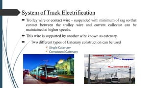
- 9. System of Track Electrification ’é┤ Trolley wire or contact wire ŌĆō suspended with minimum of sag so that contact between the trolley wire and current collector can be maintained at higher speeds. ’é┤ This wire is supported by another wire known as catenary. ’é┤ Two different types of Catenary construction can be used ’āś Single Catenary ’āś Compound Catenary
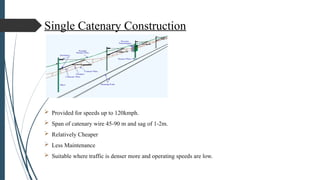
- 10. Single Catenary Construction ’āś Provided for speeds up to 120kmph. ’āś Span of catenary wire 45-90 m and sag of 1-2m. ’āś Relatively Cheaper ’āś Less Maintenance ’āś Suitable where traffic is denser more and operating speeds are low.
- 11. Compound catenary construction ’āś Provided for speeds ranges 190-224kmph. ’āś Additional wire called intermediate wire is used to increase current carrying capacity i.e., to have increased traffic density.
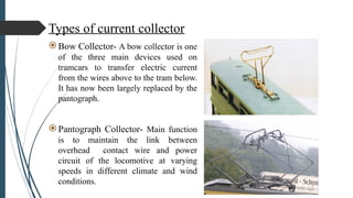
- 12. Types of current collector ’é×Bow Collector- A bow collector is one of the three main devices used on tramcars to transfer electric current from the wires above to the tram below. It has now been largely replaced by the pantograph. ’é×Pantograph Collector- Main function is to maintain the link between overhead contact wire and power circuit of the locomotive at varying speeds in different climate and wind conditions.
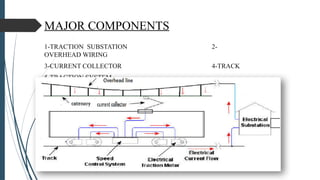
- 13. MAJOR COMPONENTS 1-TRACTION SUBSTATION 2- OVERHEAD WIRING 3-CURRENT COLLECTOR 4-TRACK 5-TRACTION SYSTEM
- 14. BLOCK DIAGRAM OF AN A.C LOCOMOTIVE
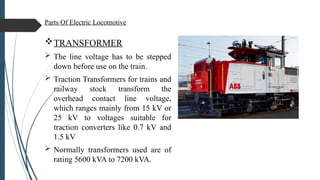
- 15. Parts Of Electric Locomotive ’üČTRANSFORMER ’āś The line voltage has to be stepped down before use on the train. ’āś Traction Transformers for trains and railway stock transform the overhead contact line voltage, which ranges mainly from 15 kV or 25 kV to voltages suitable for traction converters like 0.7 kV and 1.5 kV ’āś Normally transformers used are of rating 5600 kVA to 7200 kVA.
- 16. RECTIFIER ’āś A rectifier consist of thyristors and diodes which is used to convert AC to DC. ’āś Instead of conventional bridge rectifiers thyristors are used. ’āś A modern locomotive usually have at least two ŌĆ£Main RectifierŌĆØ.
- 17. Inverter ’é┤ The inverters are used for converting DC power from a fixed voltage DC supply into an AC output voltage of variable frequency and fixed or variable output AC voltage.
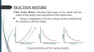
- 18. TRACTION MOTORS ’ü▒ D.C Series Motors- Develops high torque at low speeds and low torque at high speed, exact requirement of the traction units. ’é┤ Torque is independent of the line voltage and thus unaffected by the variations in the line voltage.
- 19. ’ü▒ Single phase A.C Series Motors- Starting torque is lower than dc series motor due to poor power factor at starting. ’é┤ Maximum operating voltage is limited to 400 Volts.
- 20. ’ü▒ Three Phase Induction Motors- Provides constant speed operation, developing low starting torque drawing high starting current and complicated control networks makes it unsuitable for electric traction work. ’é┤ Automatic regeneration is the main advantage in electric traction with this motor.
- 21. ELECTRICAL BRAKING We can say that it is the process of reducing speed of any rotating machine. Classified into three categories- 1.Plugging 2.Rheostatic braking 3.Regenerative braking 1)Plugging- Plugging is applied by changing phase sequence of synchronous or induction motors. The main disadvantage of this method is that here power is wasted.
- 22. 2)Rheostatic breaking-Connection are made changed from power configuration to brake configuration and resistor are inserted in motor circuit. 3) Regenerative braking- Motors become generators and feed resulting current back into supply system.
- 23. THANK YOU