Electronic governor
- 1. ELECTRONIC SPEED GOVERNOR A governor, or speed limiter, is a device used to measure and regulate the speed of a machine, such as an engine By J.Majumder Chartered Engineer MIE
- 2. SIMPLE EXPLANATION OF WORKING OF GOVERNOR âĒ Speed Governor is an electromechanical device in diesel engine. âĒ Its function is to maintain & control the speed of the engine by controlling the amount of fuel to engine. The core concept in power generation is that, the speed of engine or turbine must be constant or +-x of it. A fluctuation in speed would cause fluctuation in voltage and frequency. âĒ Governor maintain the speed of running engine by controlling the amount of fuel supply to engine. If the speed is low or high other than nominal value, then it increase or decrease the amount of fuel to engine. The signal governor receives from a certain control system.
- 3. THE SPEED SET POINT ON THE ROAD IS 100 KM/H AND MAINTAIN THE SPEED BY THE ACCELERATOR DEPENDING OF DRIVING UP-OR DOWNHILL. Governor Governor
- 4. INCREASED LOAD 100 The car starts up the hill, load increases, speed decreases.âĒ The actual speed is less than desired speed.âĒ Driver increases the fuel to increase the speed, which returns the actual speed to the desired speed.âĒ Before the actual speed reaches the desired speed, the driver reduces the fuel to prevent overshoot of speed. This is called Compensation and is adjusted to match the response time of the prime mover.âĒ It takes more fuel to pick up load than to maintain load
- 5. DECREASED LOAD 100 The car starts down the hill, load decreases, speed increases.âĒ Actual speed is greater than desired speed.âĒ Driver decreases fuel to decrease speed, which returns the actual speed to desired speed.âĒ Before the actual speed reaches the desired speed, the driver increases the fuel to prevent overshoot of speed. This is called Compensation and is adjusted to match the response time of the prime mover.
- 6. CONTROL LOOP OF A DIESEL ENGINE The governor functions the same as the car driver.âĒ It automatically changes the Fuel Flow to maintain the desired speed or load.
- 7. ELECTRONIC SPEED GOVERNOR When used as an automatic control system for operation or process in which feedback in a closed path or group of paths to maintain output at a desired level.âĒ If parameter(s) of the loop change, it will effect the entire loop and fuel will automatically be corrected to maintain the desired setpoint.
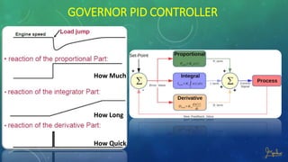
- 8. GOVERNOR PID CONTROLLER How Much How Long How Quick
- 9. RESPONSE OF PID CONTROLLER
- 10. PID CONTROLLER The main task of the governor controller is to convert the induced frequency read by the MPU into a DC voltage signal and then compare it with setting voltage (frequency). The result will be calculated by PID and then finally be output to actuator
- 11. POSSIBLE OPERATING MODES âĒ Speed droop especially used at infinite grid parallel operation âĒ Isochronous load sharing especially used at island operated plants âĒ Master / Slave load sharing especially used at ships propulsion plants, running two engines on one shaft
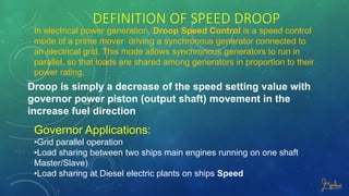
- 12. DEFINITION OF SPEED DROOP Droop is simply a decrease of the speed setting value with governor power piston (output shaft) movement in the increase fuel direction Governor Applications: âĒGrid parallel operation âĒLoad sharing between two ships main engines running on one shaft Master/Slave) âĒLoad sharing at Diesel electric plants on ships Speed In electrical power generation, Droop Speed Control is a speed control mode of a prime mover driving a synchronous generator connected to an electrical grid. This mode allows synchronous generators to run in parallel, so that loads are shared among generators in proportion to their power rating.
- 13. WHY SHOULD YOU USE DROOP CONTROL? Suppose that a generator is paralleled with the utility grid. If it is considered as an infinite bus, the utility grid will determine the generator frequency (speed) and voltage. When the speed (and frequency) setpoint is slightly lower, the speed governor will fully close the fuel supply in attempt to lower the frequency. Is the setpoint slightly higher, the speed governor will fully open the fuel supply. For the automatic voltage regulator and the reactive power something similar happens. To solve these problems, we use droop controls.
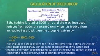
- 15. CALCULATION OF SPEED DROOP if the turbine is rated at 3000 rpm, and the machine speed reduces from 3000 rpm to 2880 rpm when it is loaded from no load to base load, then the droop % is given by = (3000 â 2880) / 3000 = 4% If all engines in a droop system do not have the same droop setting, they will not share loads proportionally with the same speed settings. If the system load changes, the system speed/frequency will also change but the percent of load on each engine-generator set will not be changed proportionately.
- 18. GENERATOR LOAD SHARING If Gen #1 Droop is a % and Gen # 2 b % and total load X Then Load taken by #1 Gen = X . a / (a+ b) Load taken by #2 Gen = X . b / (a+ b)
- 19. ISOCHRONOUS GOVERNOR CONSTANT SPEED No change in speed setting with an change in load Applications: âĒGrid parallel operation for frequency stabilization âĒLoad sharing at Island Power Stations
- 22. LAYOUT MASTER /SLAVE OPERATION
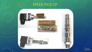
- 24. SPEED PICK UP
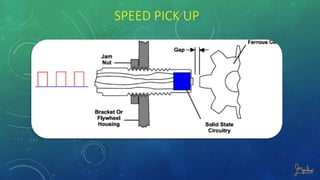
- 25. SPEED PICK UP F = number of teeth à engine speed (RPM) / 60. This frequency is proportional to the engine speed.
- 26. SPEED PICK UP
- 27. MAGNETIC SPEED PICK UP
- 30. ADJUSTMENT OF ELECTRONIC GOVERNOR Ramp Time can be set from 3 up to 20 seconds. The Ramp Time is the length of time from IDLE to the rated Run Speed. Droop operation is obtained by setting the Droop potentiometer. Moving Droop Pot clockwise increases the Droop. The amount of Droop for a given setting If GAIN or INT. (Integration) is over adjusted, it causes the engine speed to oscillate. Repetitively increasing and decreasing the GAIN and INT. arrangement can help to obtain the best performance.


