


![Problems
• A 100MHz carrier wave is frequency modulated by a 10KHz sinusoidal modulating
signal. If the maximum frequency deviation is 50KHz, find the modulation index.
Also find Carrier Swing? [ 5 Marks]
• A 15KHz audio signal is used to frequency modulate a 100MHz carrier, causing a
carrier deviation of 75KHz. Determine Modulation Index and Carrier swing?
[5 Marks]
• When the modulating frequency in FM is 600 Hz and the modulating voltage is
3V, the modulation index is 60. Calculate the maximum deviation. What is the
modulation index when the modulation frequency is reduced to 400 Hz and the
modulating voltage is simultaneously raised to 4v? [6 Marks]](https://image.slidesharecdn.com/5-230326082214-761ff308/85/embedded-systems-40-320.jpg)
![Problems
• Calculate the Carrier swing, frequency deviation and modulation index for an FM
signal which reaches a maximum frequency of 99.047MHz and a minimum
frequency of 99.023 MHz. The frequency of the modulating signal is 7KHz.
[4 Marks]
• The noise factor of a radio receiver is 15:1, calculate its noise figure. Determine
the output S/N ratio when the input S/N ratio to the receiver is 35dB.
[4 Marks]
• The initial SNR measured at the transmitter was 20 dB. In order to combat the
channel conditions, the signal power was doubled prior to transmission. What is
the new SNR at the transmitter? [6 Marks]](https://image.slidesharecdn.com/5-230326082214-761ff308/85/embedded-systems-41-320.jpg)


More Related Content
Similar to embedded systems (20)
Recently uploaded (20)


embedded systems
- 1. UNIT-5: COMMUNICATION SYSTEM MODERN COMMUNICATION SYSTEM • Communication is a process by which the information/message is transmitted from one point to another, from one person to another or from one place to another in the form of an electrical signals through some communication link. • The process of communication involves sending, receiving and processing information in electrical form. NEED FOR COMMUNICATION? • Speedy Transmission: Requires only few seconds to communicate through electronic media due the technology available for quick transmission. • Wide Coverage: The whole world has become a global village and communication around the globe requires just a second. • Low Cost: Cost of an SMS is cheaper than sending a letter by post. • Exchange of feedback: Instant exchange of feedback. • 24/7 accessibility: Can be accessed anytime.
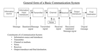
- 2. General form of a Basic Communication System Constituents of a Communication System: • Information source and transducer. • Transmitter. • Channel or medium. • Noise. • Receiver. • Output transducer and final destination.
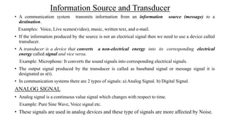
- 3. Information Source and Transducer • A communication system transmits information from an information source (message) to a destination. Examples: Voice, Live scenes(video), music, written text, and e-mail. • If the information produced by the source is not an electrical signal then we need to use a device called transducer. • A transducer is a device that converts a non-electrical energy into its corresponding electrical energy called signal and vice versa. Example: Microphone: It converts the sound signals into corresponding electrical signals. • The output signal produced by the transducer is called as baseband signal or message signal it is designated as s(t). • In communication systems there are 2 types of signals: a) Analog Signal. b) Digital Signal. ANALOG SIGNAL • Analog signal is a continuous value signal which changes with respect to time. Example: Pure Sine Wave, Voice signal etc. • These signals are used in analog devices and these type of signals are more affected by Noise.
- 4. DIGITAL SIGNAL • Digital signal consists of only 0’s & 1’s. • An analog signal can be converted into digital signal using the process called Sampling & Quantization. • An analog signal is converted into discrete time signal by the process called Sampling. The signal which is continuous in amplitude but discrete in time is called discrete signal. • The discrete signal is then quantized and represented in the form of 0’s & 1’s.
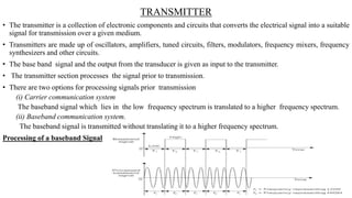
- 5. TRANSMITTER • The transmitter is a collection of electronic components and circuits that converts the electrical signal into a suitable signal for transmission over a given medium. • Transmitters are made up of oscillators, amplifiers, tuned circuits, filters, modulators, frequency mixers, frequency synthesizers and other circuits. • The base band signal and the output from the transducer is given as input to the transmitter. • The transmitter section processes the signal prior to transmission. • There are two options for processing signals prior transmission (i) Carrier communication system The baseband signal which lies in the low frequency spectrum is translated to a higher frequency spectrum. (ii) Baseband communication system. The baseband signal is transmitted without translating it to a higher frequency spectrum. Processing of a baseband Signal
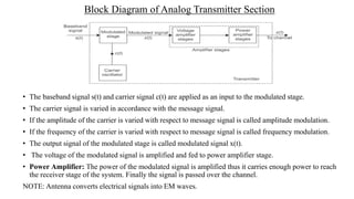
- 6. Block Diagram of Analog Transmitter Section • The baseband signal s(t) and carrier signal c(t) are applied as an input to the modulated stage. • The carrier signal is varied in accordance with the message signal. • If the amplitude of the carrier is varied with respect to message signal is called amplitude modulation. • If the frequency of the carrier is varied with respect to message signal is called frequency modulation. • The output signal of the modulated stage is called modulated signal x(t). • The voltage of the modulated signal is amplified and fed to power amplifier stage. • Power Amplifier: The power of the modulated signal is amplified thus it carries enough power to reach the receiver stage of the system. Finally the signal is passed over the channel. NOTE: Antenna converts electrical signals into EM waves.
- 7. Frequency Range & It’s Application
- 8. Communication Channel • Communication channel is a medium through which the signals is sent from one place to another. • Types of Medium: • Electrical Conductors. • Optical Media. • Free Space. • System Specific media (Eg: Water is a medium for SONAR) • The transmission medium between the transmitter and the receiver is called a Channel. • Noise gets added in the channel hence transmitted signal should have adequate power to withstand the channel noise. • The channel characteristics also impose constraints on the Bandwidth. • Bandwidth is a range of frequencies that is used for transmitting a signal. • Depending on the physical implementations, one can classify the channels in the following two groups: • Hard wired (Hardware) channels. • Soft wired (Software) channels.
- 9. Hardwired (Hardware) Channels • These are manmade structures which can be used as transmission medium. There are following three possible implementations of the hardware channels. • Transmission lines. • Waveguides. • Optical Fiber Cables (OFC). • Transmission lines are not suitable for ultra high frequency (UHF) transmission. • To transmit UHF range waveguides will be used. • Optical fiber cables are highly sophisticated transmission media in which signals are transmitted in the form of light energy. Soft-wired (Software) Channels • Natural resources which can be used as the transmission medium for signals. Example: Air or Open space and Sea water. • The signals are transmitted in the form of electromagnetic (EM) waves also called radio waves. • Radio waves travel through open space at a speed equal to that of light. where speed of light is (c=3 x 10⁸ m/s).
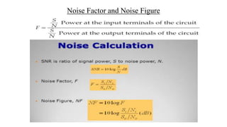
- 10. NOISE • Noise is defined as unwanted electrical energy of random and unpredictable nature. • Noise is a highly undesirable part of a communication system, and has to be minimized. • When noise is mixed with the transmitted signal, it rides over it and deteriorates its waveform. Signal to Noise Ratio (SNR) and Noise factor (F) • In judging the performance of the communication system and receiver the term SNR is used. • The SNR is a simply a number that indicates the relative strengths of the signal and the noise. • When the signal is strong and noise is weak, the SNR will be high and vice versa.
- 12. Noise Factor and Noise Figure • Noise Factor is the measure of degradation of the signal to noise ratio in a device. It is a measure of the noise introduced by the system. • Lower values indicate better performance. • Noise factor = 1  if no noise introduced
- 13. Noise Factor and Noise Figure
- 14. RECEIVER • The task of the receiver is to provide the original information to the user. • The signal received by the receiver is r(t). • This signal contains both the transmitted signal, x(t), and the noise, n(t), added to it during transmission. • A receiver is a collection of electronic components and circuits that accepts the transmitted message from the channel and converts it back into a form which a human can understand. • Receivers contain amplifiers, oscillators, mixers, tuned circuits and filters and a detector that recovers the original signal from the carrier.
- 15. Detailed block diagram of a Typical Receive Section
- 16. MULTIPLEXING • Multiplexing is a process which allows more than one signal to be transmitted through a single channel.
- 18. • Multiplexing allows the maximum possible utilization of the available bandwidth of the system. • The use of multiplexing also makes the communication system economical because more than one signal can be transmitted through a single channel. Advantages of Multiplexing
- 19. TYPES OF COMMUNICATION SYSTEMS One may categorize communication systems based on their physical infrastructure and the specifications of the signals they transmit. • Communication Systems based on Physical Infrastructure • Communication systems based on Signal specifications
- 20. Communication Systems based on Physical Infrastructure
- 21. Communication Systems based on Signal Specifications The signal specifications used to decide the type of communication include: • Nature of baseband or information signal. • Nature of the transmitted signal. Based on the nature of the baseband signal. • Analog communication systems. • Digital communication systems. Based on the nature of the transmitted signal. The two systems can then be put under following categories: • Baseband communication system. • Carrier communication system. Thus, there are four types of communication system categories based on signal specification. These are: • Analog communication system. • Digital communication system. • Baseband communication system. • Carrier communication system.
- 22. Modulation • Modulation – process of translating the low frequency baseband signal to higher frequency spectrum • Process of changing the parameters of the carrier signal, in accordance with the instantaneous values of the modulating signal. Need for Modulation • Improves Quality of reception. • Reduces Height of antenna. • Options for Multiplexing. • Bandwidth Extension. • Increased Range of Communication. • Reduced noise and interference.
- 24.  Types of Analog (Continuous Wave) Modulation  Amplitude modulation  Frequency modulation
- 25. Amplitude Modulation • Amplitude modulation (AM) -modulation technique in which the instantaneous amplitude of the carrier signal is varied in accordance with the instantaneous amplitude of the analog modulating signal to be transmitted • Modulating signal - an analog baseband signal which is random and has a low frequency • Carrier signal- a sinusoidal wave with high frequency • Variations in amplitude of carrier signal represent the information
- 26. Amplitude Modulation ‚Ä¢ The amplitude of the carrier wave is varied in accordance with the modulating signal while the frequency and phase of the carrier signal remains unchanged. ‚Ä¢ Modulating signal seems to be superimposed on the carrier signal. ‚Ä¢ Amplitude variations in the peak values of the carrier signal exactly replicates the modulating signal at different points of time which is known as an envelope. ‚Ä¢ Modulation Index (0 to 1) ùúá = Am/Ac
- 27. Frequency Modulation ‚Ä¢ Process of changing the frequency of the carrier signal in accordance with the instantaneous value of the modulating signal while keeping the amplitude and phase of the carrier constant. ‚Ä¢ The original frequency of the carrier signal is called the center frequency denoted as ùëìùëê. ‚Ä¢ Frequency deviation (‚àÜf) -The amount by which the frequency of the carrier wave changes or shifts above or below the center frequency. ‚àÜf ‚àù m(t)
- 28. Frequency Modulation ‚Ä¢ The total variation of frequency of FM wave from the lowest to highest is termed as carrier swing (CS) CS = 2√ó ‚àÜf ‚Ä¢ Modulation Index (can be >1): Œºùëì = ùêπùëüùëíùëûùë¢ùëíùëõùëêùë¶ ùëëùëíùë£ùëñùëéùë°ùëñùëúùëõ ùëÄùëúùëëùë¢ùëôùëéùë°ùëñùëõùëî ùëìùëüùëíùëûùë¢ùëíùëõùëêùë¶ = ‚àÜf ùëìùëö
- 29. CELLULAR WIRELESS NETWORKS • The cellular technology was introduced by researchers from BELL Laboratory in 1947. • For a proper cellular communication it was determined that the larger geographical area must be subdivided into a small sections called cells which uses the concept of frequency reuse to increase the capacity of a wireless and mobile telephone channel. • In a wireless communication, base stations will be used to provide a connection to all the mobile users within the coverage area and the Base Station(BS) must be connected to a central hub called Mobile Switching Center (MSC). • As the number of users increase, the infrastructure and antenna sites has to increase to provide better facility and quality of service (QOS).
- 31. Cellular Telephone System A cellular system comprises of following basic components: • Mobile Station (MS): This is the mobile handset, which is used by an user to communicate with another user. • Cell: Each Cellular service area is divided into small regions called cell (5 to 20 KM). • Base Station (BS): Each cell contains an antenna, which is controlled by a small office. • Mobile Switching Center (MSC): Each base station is controlled by a switching office called mobile switching center.
- 32. Cellular Concept and Frequency Reuse • The group of cells in a smaller areas are known as Clusters. Conversations can be handed off from cell to cell to maintain constant phone service as the user moves between cells. • Cells can be sized according to the subscriber density and demand. As the demand grows cells can be added to accommodate the growth. • Small sized cells can be used to meet the demand but it will increase the Co-Channel Interference (CCI). Thus it affects the QOS. • Frequency reuse is a concept in cellular radio system in which the total available channels are divided into a number of channel sets and each channel set is assigned to a cell.
- 33. First Generation (1G) Technology • The original cellular networks, now named as 1G, provided analog traffic channels and were designed to be an extension of the public switched telephone networks. • Users with brick - sized cell phones placed and received calls in the same fashion as landline subscribers. (Circuit switching) • The most widely deployed 1G system was the Advanced Mobile Telephone System (AMTS),developed by AT&T. • The channels (frequency bands) carry the conversations in analog using Frequency Division Multiple Access (FDMA) . • It provides speed up to 2.4Kbps. • 800MHz spectrum (25MHz bandwidth) – voice and control channels ; each 30KHz • The number of channels is inadequate for many larger areas. It has low capacity, unreliable handoff, poor voice links, and no security at all.
- 34. Second Generation (2G) Technology • Second-generation (2G) systems were developed to provide higher - quality signals, higher data rates for support of digital services and greater capacity. Key differences between 1G and 2G networks are as below: 1. Digital traffic channels: The most notable difference between the two generations is that 1G systems are almost purely analog, whereas 2G systems are digital. • In particular, 1G system is designed to support voice channels; (digital traffic is supported only by the use of a modem that converts the digital data into analog form). • 2G systems provide digital traffic channels. 2G systems readily support digital data, voice traffic is first encoded in digital form before transmitting. 2. Encryption: Because all of the user traffic, as well as control traffic, is digitized in 2G systems, it is a relatively simple matter to encrypt all of the traffic to prevent eavesdropping. All 2G systems provide this capability, whereas 1G system sends user traffic in the clear, providing no security. 3. Error detection and correction: The use of error detection and correction techniques in digital traffic stream of 2G systems is very easy. So, the result will be usually with fewer errors. 4. Channel access: In 1G system, each cell supports a number of channels. At any given time a channel is allocated to only one user. 2G systems also provide multiple channels per cell, but each channel is dynamically shared by a number of users using time division multiple access (TDMA).
- 35. Second Generation (2G) Technology • IS-136 • IS-95 • GSM
- 36. Third Generation (3G) Technology • The objective of the third generation (3G) wireless communication is to provide fairly high –speed wireless communications to support multimedia, data and video in addition to voice. The dominant technology for 3G systems is CDMA. • The design features of CDMA are:- 1. Bandwidth: An important design goal for all 3G systems is to limit channel usage to 5MHz. (GSM – 200KHz) 2. Data rate: The data rates of 144 and 384 kbps are usually supported by 3G network. Some 3G systems also provide support up to 2 Mbps for office use. 3. Multirate: The term multirate refers to the provision of multiple fixed-data-rate channels to a given user, in which different data rates are provided on different channels. The advantage of multirate is that the system can flexibly support multiple simultaneous applications from a given user. (clean/noisy environment, music) • Universal mobile telecommunication system(UMTS) and CDMA-2000 are two main 3G networks used.
- 37. FOURTH GENERATION(4G) TECHNOLOGY • LTE or Long Term Evolution is the brand name given to the efforts of 3GPP 4th Generation technology development efforts mostly in Europe and UMB (Ultra-Mobile Broadband) is the brand name for similar efforts by 3GPP2 in North America. • The High Level requirements for a 4G technology were identified as: 1. Higher spectral efficiency (bps/Hz). 2. Reduced cost per bit. 3. Increased service provisioning by lowering the cost and increasing efficiency. 4. Open interfaces as against closed technologies of the past. 5. Power consumption efficiency. 6. Scalable and flexible usage of frequency bands. • The technical specifications approved by 3GPP for the LTE project include I. Orthogonal Frequency Division Multiplexing (OFDM) II. Advanced antenna technologies such as MIMO (Multiple Input Multiple Output)
- 38. OFDMA
- 40. Problems • A 100MHz carrier wave is frequency modulated by a 10KHz sinusoidal modulating signal. If the maximum frequency deviation is 50KHz, find the modulation index. Also find Carrier Swing? [ 5 Marks] • A 15KHz audio signal is used to frequency modulate a 100MHz carrier, causing a carrier deviation of 75KHz. Determine Modulation Index and Carrier swing? [5 Marks] • When the modulating frequency in FM is 600 Hz and the modulating voltage is 3V, the modulation index is 60. Calculate the maximum deviation. What is the modulation index when the modulation frequency is reduced to 400 Hz and the modulating voltage is simultaneously raised to 4v? [6 Marks]
- 41. Problems • Calculate the Carrier swing, frequency deviation and modulation index for an FM signal which reaches a maximum frequency of 99.047MHz and a minimum frequency of 99.023 MHz. The frequency of the modulating signal is 7KHz. [4 Marks] • The noise factor of a radio receiver is 15:1, calculate its noise figure. Determine the output S/N ratio when the input S/N ratio to the receiver is 35dB. [4 Marks] • The initial SNR measured at the transmitter was 20 dB. In order to combat the channel conditions, the signal power was doubled prior to transmission. What is the new SNR at the transmitter? [6 Marks]
Editor's Notes
- #17: The main difference between tdm and tdma (also fdm/fdma, etc) is that with tdm (also fdm, etc.) the signals multiplexed (i.e. sharing a resource) come from the same node, whereas for tdma (also fdm, etc.) the signals multiplexed come from different sources/transmitters.
- #37: Configuration A (Config-WB-Code 0): 6.6, 8.85, and 12.65Ã˝kbit/s (Mandatory multi-rate configuration) Configuration B (Config-WB-Code 2): 6.6, 8.85, 12.65, and 15.85Ã˝kbit/s Configuration C (Config-WB-Code 4): 6.6, 8.85, 12.65, and 23.85Ã˝kbit/s